Sensor Test
Use this test to determine if the input tray sensors are working correctly.
1
From the Diagnostics menu, navigate to:
Input Tray Tests
>
Sensor Test
2
Select the input source. All installed sources appear.
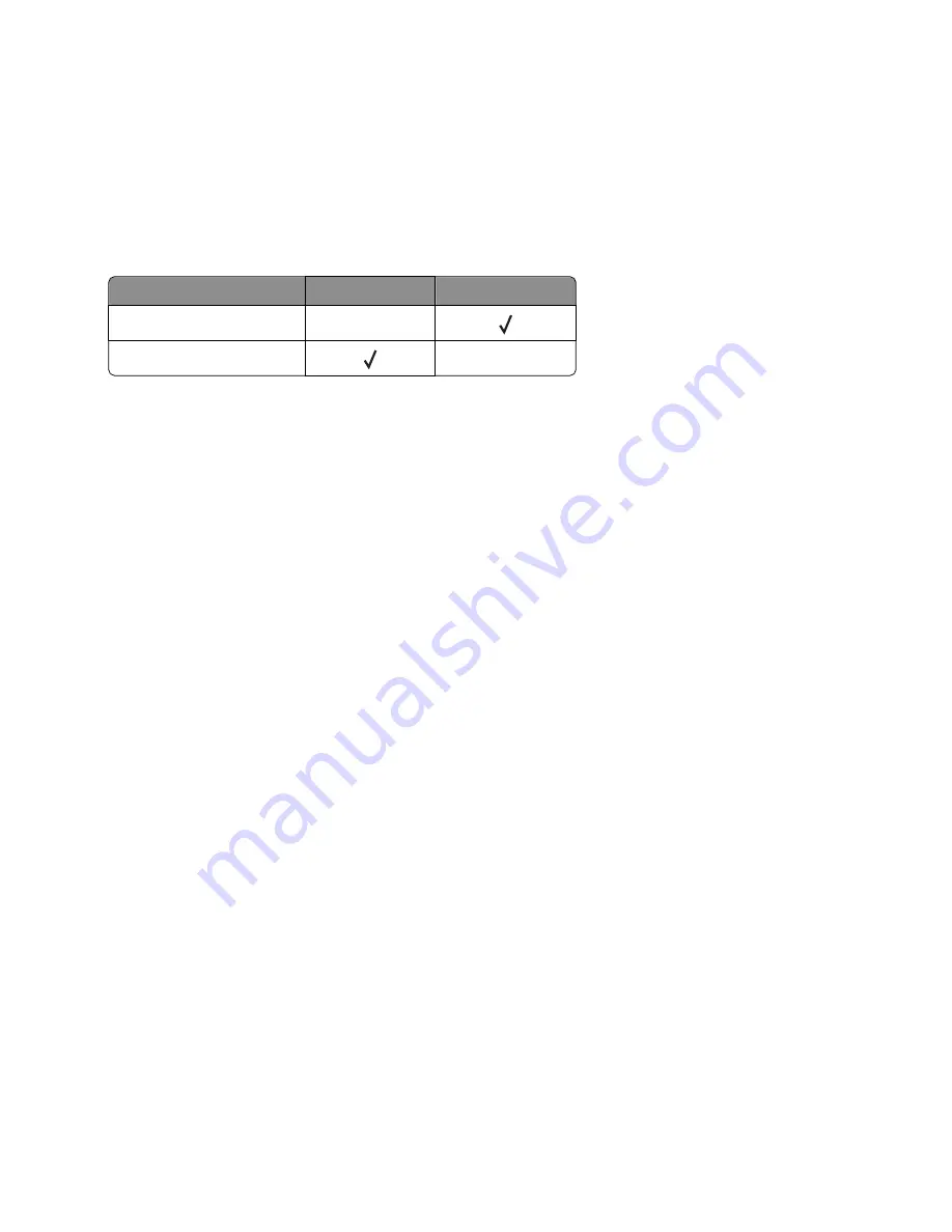
Not all sensors appear for all trays. The following table indicates which tray sensors are available for each input
source:
Input source
Tray empty sensor Pass through sensor
Optional 250
‑
/550-sheet tray
X
Multipurpose feeder
X
3
Manually actuate each sensor. The tray empty sensor can be actuated by hand; however, a sheet of paper can be
used to cover the pass through sensor.
4
Press
X
to exit the test.
Output Bin Tests
Feed Tests
This test verifies that media can be fed to a specific output bin. No information is printed on the media.
To run this test:
1
From the Diagnostics menu, navigate to:
Output Bin Tests
>
Feed Tests
2
Select the output bin into which you want the paper to exit. All installed output bins appear.
3
Select one of the following:
•
Single—Feeds a single page.
•
Continuous—Continuously feeds pages until
X
is pressed.
Sensor Test
This test verifies that the output bin sensors are working correctly.
To run this test:
1
From the Diagnostics menu, navigate to:
Output Bin Tests
>
Sensor Test
>
Standard Bin
Testing...
appears while the printer is verifying the state of the sensor.
The control panel displays the current state of the sensor.
2
Manually actuate the sensor to make it toggle between
empty
and
full
. If the sensor does not toggle, then the
sensor is malfunctioning.
3
Press
X
to exit the test.
4514
Service menus
127
Summary of Contents for M1140
Page 18: ...4514 18 ...
Page 20: ...4514 20 ...
Page 142: ...4514 142 ...
Page 197: ...b Set the spring over the plunger 4514 Repair information 197 ...
Page 204: ...3 Squeeze the latches B to release the left and right links B 4514 Repair information 204 ...
Page 228: ...10 Remove the screw C and then detach the trailing edge sensor A 4514 Repair information 228 ...
Page 229: ...11 Disconnect the two springs D 4514 Repair information 229 ...
Page 246: ...3 Swing the right cover backward to remove 4 Remove the screw D 4514 Repair information 246 ...
Page 248: ...4514 248 ...
Page 253: ...4514 253 ...
Page 255: ...Assembly 1 Covers 4514 Parts catalog 255 ...
Page 257: ...Assembly 2 Electronics 1 4514 Parts catalog 257 ...
Page 259: ...Assembly 3 Electronics 2 4 3 2 1 6 5 4514 Parts catalog 259 ...
Page 261: ...4514 Parts catalog 261 ...
Page 262: ...Assembly 4 Frame 4514 Parts catalog 262 ...
Page 264: ...4514 Parts catalog 264 ...
Page 265: ...Assembly 5 Option trays 3 4 5 6 1 2 4514 Parts catalog 265 ...
Page 268: ...4514 Parts catalog 268 ...
Page 270: ...4514 270 ...
Page 274: ...4514 274 ...
Page 276: ...4514 276 ...
Page 298: ...4514 Part number index 298 ...
Page 302: ...4514 Part name index 302 ...
Page 303: ......


