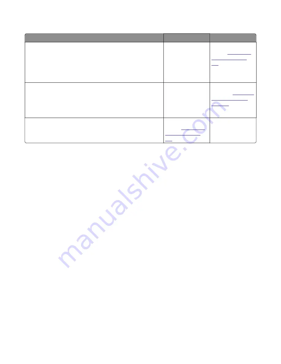
Cooling fan service check
Action
Yes
No
Step 1
a
Make sure that the cable JFAN1 is properly connected to the controller
board.
b
Check if the cooling fan is rotating properly.
Is it rotating properly?
Go to step 2.
Replace the cooling
fan. See
“Cooling fan
removal” on page
186
.
Step 2
a
Turn off the printer, and disconnect JFAN1 from the controller board.
b
Turn on the printer, and measure the voltage across JFAN1.
Is the voltage approximately 24 V?
Go to step 3.
Replace the controller
board. See
“Controller
board removal” on
page 187
.
Step 3
Is the fan idle?
Replace the cooling
fan. See
“Cooling fan
removal” on page
186
.
The problem is solved.
Steps before starting the 9yy service checks
Before starting the service checks in this section, you will need to retrieve certain information. This will aid your next
level of support in diagnosing the problem before replacing the controller board.
Warning—Potential Damage:
Do not replace the controller board unless directed by your next level of support.
1
Collect the history information and firmware logs (Fwdebug and logs.tar.gz) from the SE menu.
2
Collect the settings from the menu settings page.
3
Collect information from the user.
Note:
Not all of the items can be retrieved from the printer you are working on.
A. Collecting the history information from the SE menu
Note:
Make sure your printer is connected to a network or to a print server.
1
From a Web browser, type
http://printer_IP_address/se
, and then press
Enter
.
Notes:
•
printer_IP_address
is the TCP/IP address of the printer
•
se
is required to access the printer diagnostic information
2
Click
History Information
, copy all information, and then save it as a text file.
3
E-mail the text file to your next level of support.
B. Collecting the firmware logs (Fwdebug and logs.tar.gz) from the SE menu
Notes:
•
Make sure your printer is connected to a network or to a print server.
4514
Diagnostic information
94
Summary of Contents for M1140
Page 18: ...4514 18 ...
Page 20: ...4514 20 ...
Page 142: ...4514 142 ...
Page 197: ...b Set the spring over the plunger 4514 Repair information 197 ...
Page 204: ...3 Squeeze the latches B to release the left and right links B 4514 Repair information 204 ...
Page 228: ...10 Remove the screw C and then detach the trailing edge sensor A 4514 Repair information 228 ...
Page 229: ...11 Disconnect the two springs D 4514 Repair information 229 ...
Page 246: ...3 Swing the right cover backward to remove 4 Remove the screw D 4514 Repair information 246 ...
Page 248: ...4514 248 ...
Page 253: ...4514 253 ...
Page 255: ...Assembly 1 Covers 4514 Parts catalog 255 ...
Page 257: ...Assembly 2 Electronics 1 4514 Parts catalog 257 ...
Page 259: ...Assembly 3 Electronics 2 4 3 2 1 6 5 4514 Parts catalog 259 ...
Page 261: ...4514 Parts catalog 261 ...
Page 262: ...Assembly 4 Frame 4514 Parts catalog 262 ...
Page 264: ...4514 Parts catalog 264 ...
Page 265: ...Assembly 5 Option trays 3 4 5 6 1 2 4514 Parts catalog 265 ...
Page 268: ...4514 Parts catalog 268 ...
Page 270: ...4514 270 ...
Page 274: ...4514 274 ...
Page 276: ...4514 276 ...
Page 298: ...4514 Part number index 298 ...
Page 302: ...4514 Part name index 302 ...
Page 303: ......


