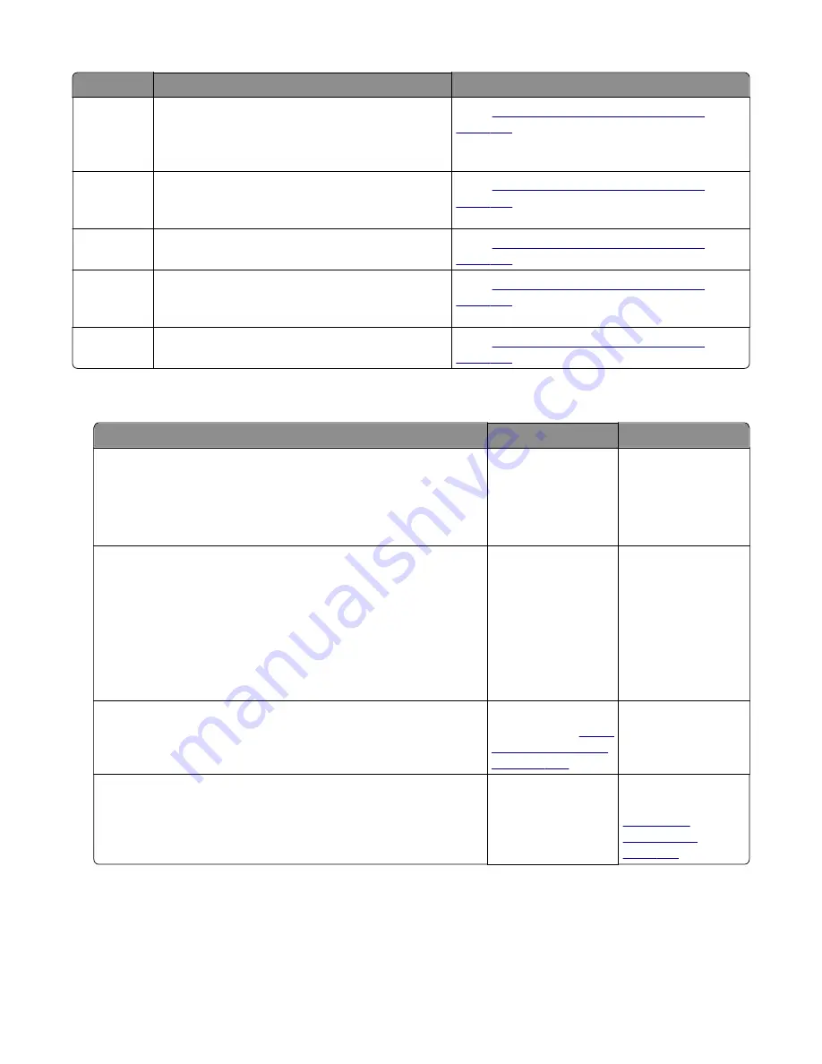
Error code
Description
Action
244.45
Motor 2 (Separator/Passthru) motor PWM
overflow error (underspeed). Motor underspeed
(max PWM and motor underspeed, typical
accordion jam).
“Option tray jam service check” on
.
244.46
Motor 2 (Separator/Passthru) motor ramp (end
ramp - did not reach speed, typical pack feed
paper jam).
“Option tray jam service check” on
.
244.47
Motor 3 motor stalled.
Go to
“Option tray jam service check” on
.
244.48
Motor 3 motor PWM overflow error (underspeed).
Motor underspeed (max PWM and motor
underspeed, typical accordion jam).
“Option tray jam service check” on
.
244.49
Motor 3 motor ramp (end ramp - did not reach
speed, typical pack feed paper jam).
“Option tray jam service check” on
.
Option tray jam service check
Action
Yes
No
Step 1
Restart the printer.
Does it fail to complete the POST sequence and display a 242.01
error?
Replace the option
tray.
Go to step 2.
Step 2
a
POR into the Diagnostics menu and perform a feed test:
Diagnostics Menu
>
Input Tray Tests
>
Feed Test
> Select an
option tray >
Continuous
b
Cancel the test after five pages.
Does the printer successfully feed the five pages into the output
bin?
The problem is
solved.
Go to step 3.
Step 3
Does the printer display a 242.06 error?
Replace the ACM
assembly. See
Go to step 4.
Step 4
Check the pick roller assembly.
Is it free of wear or damage?
Go to step 5.
Replace the pick
roller assembly. See
“Pick roller
removal” on
page 319
4514-6xx
Diagnostics and troubleshooting
108
Summary of Contents for M3150
Page 12: ...Part name index 393 4514 6xx Table of contents 12 ...
Page 20: ...4514 6xx 20 ...
Page 38: ...4514 6xx 38 ...
Page 172: ...4514 6xx 172 ...
Page 246: ...3 Remove two screws A and then remove the cooling fan mount A 4514 6xx Parts removal 246 ...
Page 256: ...5 Remove the four screws B and then remove the right front mount B 4514 6xx Parts removal 256 ...
Page 260: ...b Set the spring over the plunger 4514 6xx Parts removal 260 ...
Page 277: ...3 Squeeze the latches B to release the left and right links B 4514 6xx Parts removal 277 ...
Page 300: ...3 Place the printer on its rear side 4 Release the sensor flag A 4514 6xx Parts removal 300 ...
Page 301: ...5 Remove the screw B 6 Remove the sensor flag bracket C 4514 6xx Parts removal 301 ...
Page 323: ...3 Swing the right cover backward to remove 4 Remove the screw D 4514 6xx Parts removal 323 ...
Page 333: ...4514 6xx 333 ...
Page 335: ...Assembly 1 Covers 4514 6xx Parts catalog 335 ...
Page 338: ...4514 6xx Parts catalog 338 ...
Page 339: ...Assembly 2 Electronics 1 1 2 3 4 5 7 9 10 11 6 8 12 4514 6xx Parts catalog 339 ...
Page 342: ...4514 6xx Parts catalog 342 ...
Page 343: ...Assembly 3 Electronics 2 4 3 2 1 5 6 8 9 7 4514 6xx Parts catalog 343 ...
Page 345: ...4514 6xx Parts catalog 345 ...
Page 346: ...Assembly 4 Frame 10 11 12 13 14 9 1 5 6 7 8 4 4 2 3 4514 6xx Parts catalog 346 ...
Page 349: ...Assembly 5 Option trays 3 4 5 6 1 2 4514 6xx Parts catalog 349 ...
Page 354: ...4514 6xx Parts catalog 354 ...
Page 356: ...4514 6xx Parts catalog 356 ...
Page 364: ...4514 6xx 364 ...
Page 376: ...4514 6xx 376 ...
Page 386: ...4514 6xx Index 386 ...
Page 392: ...4514 6xx Part number index 392 ...
Page 398: ...4514 6xx Part name index 398 ...


