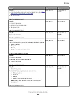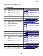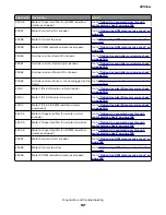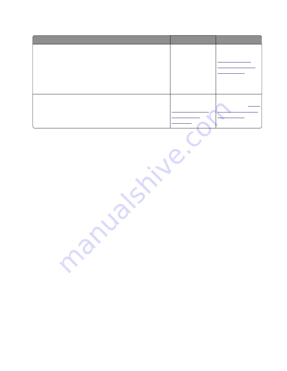
ACM service check
Action
Yes
No
Step 1
Check the pick/lift motor gearbox for proper operation.
a
POR into the Diagnostics menu and perform a feed test:
Diagnostics Menu
>
Input Tray Tests
>
Feed Test
>
Tray 1
b
Check if the pick/lift motor gearbox rotates on each pick.
Does it rotate during the feed test?
Go to step 2.
Replace the pick/lift
motor gearbox. See
“Pick/Lift motor
gearbox removal”
on page 305
.
Step 2
Lower the ACM assembly, and rotate the pick roller toward the front
without touching the pick tire.
Does it rotate properly?
Replace the
controller board. See
“Controller board
removals” on
page 247
Replace the ACM
assembly. See
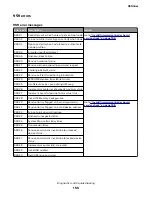
Procedure before starting the 9yy service checks
You will need to retrieve certain information. This information will aid your next level of support in diagnosing
the problem before replacing the controller board.
Warning—Potential Damage:
Do not replace the controller board unless directed by your next level of
support.
1
Collect the history information and firmware logs (Fwdebug and logs.tar.gz) from the SE menu.
2
Collect the settings from the menu settings page.
3
Collect information from the user.
Note:
Not all of the items are retrievable from the printer you are working on.
A. Collecting the history information from the SE menu
Note:
Make sure that your printer is connected to a network or to a print server.
1
Open a Web browser, type
http://printer_IP_address/se
, and then press
Enter
.
Notes:
•
printer_IP_address
is the TCP/IP address of the printer
•
se
is required to access the printer diagnostic information
2
Click
History Information
, copy all information, and then save it as a text file.
3
E-mail the text file to your next level of support.
B. Collecting the firmware logs (Fwdebug and logs.tar.gz) from the SE menu
Notes:
•
Make sure that your printer is connected to a network or to a print server.
4514-6xx
Diagnostics and troubleshooting
147
Summary of Contents for M3150
Page 12: ...Part name index 393 4514 6xx Table of contents 12 ...
Page 20: ...4514 6xx 20 ...
Page 38: ...4514 6xx 38 ...
Page 172: ...4514 6xx 172 ...
Page 246: ...3 Remove two screws A and then remove the cooling fan mount A 4514 6xx Parts removal 246 ...
Page 256: ...5 Remove the four screws B and then remove the right front mount B 4514 6xx Parts removal 256 ...
Page 260: ...b Set the spring over the plunger 4514 6xx Parts removal 260 ...
Page 277: ...3 Squeeze the latches B to release the left and right links B 4514 6xx Parts removal 277 ...
Page 300: ...3 Place the printer on its rear side 4 Release the sensor flag A 4514 6xx Parts removal 300 ...
Page 301: ...5 Remove the screw B 6 Remove the sensor flag bracket C 4514 6xx Parts removal 301 ...
Page 323: ...3 Swing the right cover backward to remove 4 Remove the screw D 4514 6xx Parts removal 323 ...
Page 333: ...4514 6xx 333 ...
Page 335: ...Assembly 1 Covers 4514 6xx Parts catalog 335 ...
Page 338: ...4514 6xx Parts catalog 338 ...
Page 339: ...Assembly 2 Electronics 1 1 2 3 4 5 7 9 10 11 6 8 12 4514 6xx Parts catalog 339 ...
Page 342: ...4514 6xx Parts catalog 342 ...
Page 343: ...Assembly 3 Electronics 2 4 3 2 1 5 6 8 9 7 4514 6xx Parts catalog 343 ...
Page 345: ...4514 6xx Parts catalog 345 ...
Page 346: ...Assembly 4 Frame 10 11 12 13 14 9 1 5 6 7 8 4 4 2 3 4514 6xx Parts catalog 346 ...
Page 349: ...Assembly 5 Option trays 3 4 5 6 1 2 4514 6xx Parts catalog 349 ...
Page 354: ...4514 6xx Parts catalog 354 ...
Page 356: ...4514 6xx Parts catalog 356 ...
Page 364: ...4514 6xx 364 ...
Page 376: ...4514 6xx 376 ...
Page 386: ...4514 6xx Index 386 ...
Page 392: ...4514 6xx Part number index 392 ...
Page 398: ...4514 6xx Part name index 398 ...


