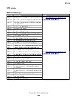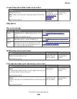
Action
Yes
No
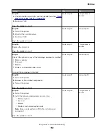
Step 7
Using the scanner, perform a one-page copy job in color.
Does the problem remain?
Go to step 12.
Go to step 8.
Step 8
a
Turn off the printer.
b
At the rear of the printer, connect the network cable, USB cable,
and fax line.
c
Turn on the printer.
Does the problem remain?
Go to step 9.
Go to step 10.
Step 9
a
Start the printer in
Invalid engine mode
. See
b
Check if an
Invalid Engine Code
message appears.
Does an
Invalid Engine Code
message appear?
Go to step 10.
Contact the next
level of support.
Step 10
Using the Device Settings report that is printed in step 5, check if
the firmware level is older than the latest available version.
Is the firmware version older, and does the customer agree to
update the firmware?
Go to step 11.
Contact the next
level of support.
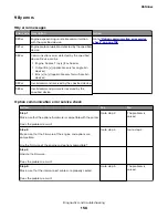
Step 11
Update the firmware to the latest version.
Does the problem remain?
Go to step 12.
The problem is
solved.
Step 12
a
Turn off the printer.
b
Make sure that all the cables on the controller board and
scanner are properly connected.
c
Turn on the printer.
d
From the control panel, navigate to the
Reports
menu, and then
select
Device Statistics
and
Device Settings
.
e
For MFPs, perform a one-page copy and scan job in color.
Does the problem remain?
Go to step 13.
The problem is
solved.
Step 13
Check if a hard disk installed.
Is a hard disk installed?
Go to step 14.
Go to step 17.
4514-6xx
Diagnostics and troubleshooting
150
Summary of Contents for M3150
Page 12: ...Part name index 393 4514 6xx Table of contents 12 ...
Page 20: ...4514 6xx 20 ...
Page 38: ...4514 6xx 38 ...
Page 172: ...4514 6xx 172 ...
Page 246: ...3 Remove two screws A and then remove the cooling fan mount A 4514 6xx Parts removal 246 ...
Page 256: ...5 Remove the four screws B and then remove the right front mount B 4514 6xx Parts removal 256 ...
Page 260: ...b Set the spring over the plunger 4514 6xx Parts removal 260 ...
Page 277: ...3 Squeeze the latches B to release the left and right links B 4514 6xx Parts removal 277 ...
Page 300: ...3 Place the printer on its rear side 4 Release the sensor flag A 4514 6xx Parts removal 300 ...
Page 301: ...5 Remove the screw B 6 Remove the sensor flag bracket C 4514 6xx Parts removal 301 ...
Page 323: ...3 Swing the right cover backward to remove 4 Remove the screw D 4514 6xx Parts removal 323 ...
Page 333: ...4514 6xx 333 ...
Page 335: ...Assembly 1 Covers 4514 6xx Parts catalog 335 ...
Page 338: ...4514 6xx Parts catalog 338 ...
Page 339: ...Assembly 2 Electronics 1 1 2 3 4 5 7 9 10 11 6 8 12 4514 6xx Parts catalog 339 ...
Page 342: ...4514 6xx Parts catalog 342 ...
Page 343: ...Assembly 3 Electronics 2 4 3 2 1 5 6 8 9 7 4514 6xx Parts catalog 343 ...
Page 345: ...4514 6xx Parts catalog 345 ...
Page 346: ...Assembly 4 Frame 10 11 12 13 14 9 1 5 6 7 8 4 4 2 3 4514 6xx Parts catalog 346 ...
Page 349: ...Assembly 5 Option trays 3 4 5 6 1 2 4514 6xx Parts catalog 349 ...
Page 354: ...4514 6xx Parts catalog 354 ...
Page 356: ...4514 6xx Parts catalog 356 ...
Page 364: ...4514 6xx 364 ...
Page 376: ...4514 6xx 376 ...
Page 386: ...4514 6xx Index 386 ...
Page 392: ...4514 6xx Part number index 392 ...
Page 398: ...4514 6xx Part name index 398 ...


