Action
Yes
No
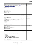
Step 5
Make sure that both ends of the interconnect cables are properly
connected to the controller board and engine options card.
Does the problem remain?
Go to step 6.
The problem is
solved.
Step 6
Check the option for damage, and replace if necessary.
Does the problem remain?
Go to step 7.
The problem is
solved.
Step 7
Check the controller board for damage, and replace if necessary.
Does the problem remain?
Contact the next
level of support.
The problem is
solved.
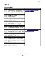
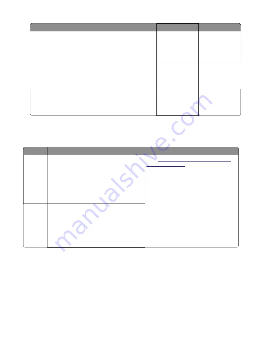
99y errors
99y error messages
Error code Description
Action
990.xx
An equipment check condition has occurred in the
specified device, but the device is unable to identify
the exact component failure. The device can be:
•
Engine, Duplex, Tray [x], Env Feeder
•
Output Bin [x] (applicable only for single bin
devices)
•
Bins [x] to [y] (applicable only for multiple bin
devices)
“Option communication error service
.
991.xx
The specified device has detected an equipment
check in its controller board. The device can be:
•
Engine, Duplex, Tray [x], Env Feeder
•
Output Bin [x] (applicable only for single bin
devices)
•
Bins [x] to [y] (applicable only for multiple bin
devices)
4514-6xx
Diagnostics and troubleshooting
159
Summary of Contents for M3150
Page 12: ...Part name index 393 4514 6xx Table of contents 12 ...
Page 20: ...4514 6xx 20 ...
Page 38: ...4514 6xx 38 ...
Page 172: ...4514 6xx 172 ...
Page 246: ...3 Remove two screws A and then remove the cooling fan mount A 4514 6xx Parts removal 246 ...
Page 256: ...5 Remove the four screws B and then remove the right front mount B 4514 6xx Parts removal 256 ...
Page 260: ...b Set the spring over the plunger 4514 6xx Parts removal 260 ...
Page 277: ...3 Squeeze the latches B to release the left and right links B 4514 6xx Parts removal 277 ...
Page 300: ...3 Place the printer on its rear side 4 Release the sensor flag A 4514 6xx Parts removal 300 ...
Page 301: ...5 Remove the screw B 6 Remove the sensor flag bracket C 4514 6xx Parts removal 301 ...
Page 323: ...3 Swing the right cover backward to remove 4 Remove the screw D 4514 6xx Parts removal 323 ...
Page 333: ...4514 6xx 333 ...
Page 335: ...Assembly 1 Covers 4514 6xx Parts catalog 335 ...
Page 338: ...4514 6xx Parts catalog 338 ...
Page 339: ...Assembly 2 Electronics 1 1 2 3 4 5 7 9 10 11 6 8 12 4514 6xx Parts catalog 339 ...
Page 342: ...4514 6xx Parts catalog 342 ...
Page 343: ...Assembly 3 Electronics 2 4 3 2 1 5 6 8 9 7 4514 6xx Parts catalog 343 ...
Page 345: ...4514 6xx Parts catalog 345 ...
Page 346: ...Assembly 4 Frame 10 11 12 13 14 9 1 5 6 7 8 4 4 2 3 4514 6xx Parts catalog 346 ...
Page 349: ...Assembly 5 Option trays 3 4 5 6 1 2 4514 6xx Parts catalog 349 ...
Page 354: ...4514 6xx Parts catalog 354 ...
Page 356: ...4514 6xx Parts catalog 356 ...
Page 364: ...4514 6xx 364 ...
Page 376: ...4514 6xx 376 ...
Page 386: ...4514 6xx Index 386 ...
Page 392: ...4514 6xx Part number index 392 ...
Page 398: ...4514 6xx Part name index 398 ...


