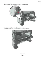
UICC removals
Critical information for controller board or UICC replacement
Warning—Potential Damage:
Replace only one of the following components at a time:
•
UICC
•
Controller board
To replace a component, and to test whether the problem is resolved:
1
Replace the affected component.
Warning—Potential Damage:
Do not perform a POR (Power
‑
On Reset) until the problem is resolved. If a
POR is performed at this point, the replacement part can no longer be used in another printer and must
be returned to the manufacturer.
2
Enter the Diagnostics Menu. The Diagnostics Menu allows you to temporarily use the replacement part.
Warning—Potential Damage:
Some printers will automatically perform a POR if the Diagnostics Menu is
not opened within five seconds. If a POR is performed at this point, the replacement part can no longer
be used in another printer and must be returned to the manufacturer.
3
Use the Diagnostics Menu to test the replacement part. Do a feed test to check if the problem is resolved.
•
If the problem is not resolved—Turn off the printer, and then reinstall the old part.
•
If the problem is resolved—Perform a POR.
Removal procedure
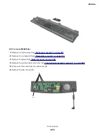
UICC removal (MS510dn and MS610dn)
1
Remove the right cover. See
“Right cover removal” on page 241
.
2
Remove the nameplate. See
“Nameplate removals” on page 263
3
Remove the bezel. See
4
Remove the control panel assembly. See
“Control panel assembly removals” on page 265
5
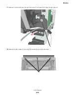
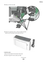
Remove the cable from the connector (A).
4514-6xx
Parts removal
271
Summary of Contents for M3150
Page 12: ...Part name index 393 4514 6xx Table of contents 12 ...
Page 20: ...4514 6xx 20 ...
Page 38: ...4514 6xx 38 ...
Page 172: ...4514 6xx 172 ...
Page 246: ...3 Remove two screws A and then remove the cooling fan mount A 4514 6xx Parts removal 246 ...
Page 256: ...5 Remove the four screws B and then remove the right front mount B 4514 6xx Parts removal 256 ...
Page 260: ...b Set the spring over the plunger 4514 6xx Parts removal 260 ...
Page 277: ...3 Squeeze the latches B to release the left and right links B 4514 6xx Parts removal 277 ...
Page 300: ...3 Place the printer on its rear side 4 Release the sensor flag A 4514 6xx Parts removal 300 ...
Page 301: ...5 Remove the screw B 6 Remove the sensor flag bracket C 4514 6xx Parts removal 301 ...
Page 323: ...3 Swing the right cover backward to remove 4 Remove the screw D 4514 6xx Parts removal 323 ...
Page 333: ...4514 6xx 333 ...
Page 335: ...Assembly 1 Covers 4514 6xx Parts catalog 335 ...
Page 338: ...4514 6xx Parts catalog 338 ...
Page 339: ...Assembly 2 Electronics 1 1 2 3 4 5 7 9 10 11 6 8 12 4514 6xx Parts catalog 339 ...
Page 342: ...4514 6xx Parts catalog 342 ...
Page 343: ...Assembly 3 Electronics 2 4 3 2 1 5 6 8 9 7 4514 6xx Parts catalog 343 ...
Page 345: ...4514 6xx Parts catalog 345 ...
Page 346: ...Assembly 4 Frame 10 11 12 13 14 9 1 5 6 7 8 4 4 2 3 4514 6xx Parts catalog 346 ...
Page 349: ...Assembly 5 Option trays 3 4 5 6 1 2 4514 6xx Parts catalog 349 ...
Page 354: ...4514 6xx Parts catalog 354 ...
Page 356: ...4514 6xx Parts catalog 356 ...
Page 364: ...4514 6xx 364 ...
Page 376: ...4514 6xx 376 ...
Page 386: ...4514 6xx Index 386 ...
Page 392: ...4514 6xx Part number index 392 ...
Page 398: ...4514 6xx Part name index 398 ...


