Cleaning the printer
Note:
You may need to perform this task after every few months.
Warning—Potential Damage:
Damage to the printer caused by improper handling is not covered by the
printer warranty.
1
Make sure that the printer is turned off and unplugged from the electrical outlet.
CAUTION—SHOCK HAZARD:
To avoid the risk of electrical shock when cleaning the exterior of the
printer, unplug the power cord from the electrical outlet and disconnect all cables from the printer
before proceeding.
2
Remove paper from the standard bin and multipurpose feeder.
3
Remove any dust, lint, and pieces of paper around the printer using a soft brush or vacuum.
4
Dampen a clean, lint-free cloth with water, and use it to wipe the outside of the printer.
Warning—Potential Damage:
Do not use household cleaners or detergents to prevent damage to the
exterior of the printer.
5
Make sure all areas of the printer are dry before sending a new print job.
Cleaning the printhead lenses
Note:
This is applicable only to models with galvo LSU. To determine whether the LSU is galvo, check the
serial number of the printer. The sixth digit character assigned should be in the 0–9 or B–N range (Example:
4514 20HH 007CR).
1
Open the front door.
2
Remove the toner cartridge and imaging unit.
3
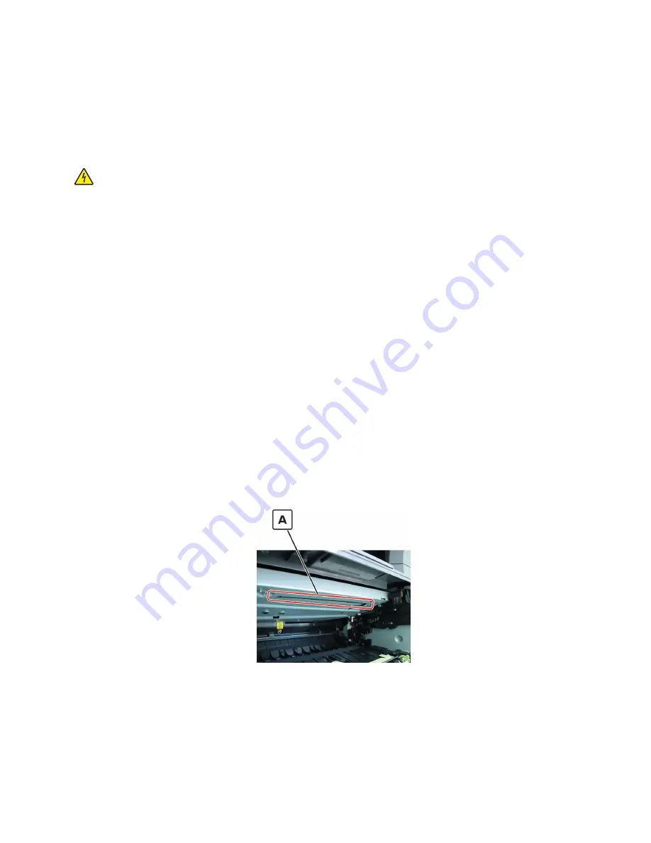
From the printhead access opening (A) in the top of the frame at the front of the printer, find the printhead
lens.
4
Insert a soft, lint
‑
free cloth in the opening, and gently move the cloth back and forth along the surface of
the lens to clean it.
5
Repeat step 4.
6
Reinstall the imaging unit and toner cartridge.
7
Close the front door.
4514-6xx
Maintenance
332
Summary of Contents for M3150
Page 12: ...Part name index 393 4514 6xx Table of contents 12 ...
Page 20: ...4514 6xx 20 ...
Page 38: ...4514 6xx 38 ...
Page 172: ...4514 6xx 172 ...
Page 246: ...3 Remove two screws A and then remove the cooling fan mount A 4514 6xx Parts removal 246 ...
Page 256: ...5 Remove the four screws B and then remove the right front mount B 4514 6xx Parts removal 256 ...
Page 260: ...b Set the spring over the plunger 4514 6xx Parts removal 260 ...
Page 277: ...3 Squeeze the latches B to release the left and right links B 4514 6xx Parts removal 277 ...
Page 300: ...3 Place the printer on its rear side 4 Release the sensor flag A 4514 6xx Parts removal 300 ...
Page 301: ...5 Remove the screw B 6 Remove the sensor flag bracket C 4514 6xx Parts removal 301 ...
Page 323: ...3 Swing the right cover backward to remove 4 Remove the screw D 4514 6xx Parts removal 323 ...
Page 333: ...4514 6xx 333 ...
Page 335: ...Assembly 1 Covers 4514 6xx Parts catalog 335 ...
Page 338: ...4514 6xx Parts catalog 338 ...
Page 339: ...Assembly 2 Electronics 1 1 2 3 4 5 7 9 10 11 6 8 12 4514 6xx Parts catalog 339 ...
Page 342: ...4514 6xx Parts catalog 342 ...
Page 343: ...Assembly 3 Electronics 2 4 3 2 1 5 6 8 9 7 4514 6xx Parts catalog 343 ...
Page 345: ...4514 6xx Parts catalog 345 ...
Page 346: ...Assembly 4 Frame 10 11 12 13 14 9 1 5 6 7 8 4 4 2 3 4514 6xx Parts catalog 346 ...
Page 349: ...Assembly 5 Option trays 3 4 5 6 1 2 4514 6xx Parts catalog 349 ...
Page 354: ...4514 6xx Parts catalog 354 ...
Page 356: ...4514 6xx Parts catalog 356 ...
Page 364: ...4514 6xx 364 ...
Page 376: ...4514 6xx 376 ...
Page 386: ...4514 6xx Index 386 ...
Page 392: ...4514 6xx Part number index 392 ...
Page 398: ...4514 6xx Part name index 398 ...


