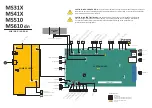
POWER SUPPLY
20
PINS
PCN1
PCN2
4 PINS
2 PINS
PCN3
3P
IN
S
PCN5
SW1
PCN6
IMAGING UNIT
CONTACTS(OPC & CHARGE)
TRANSFER ROLL SPRING
PCN4
TO
FU
SE
R
ASSE
MBL
Y
SYSTEM BOARD
PINS
JARW2
PINS
JGLV1 / JMIRR1
PINS
JCVR1
PINS
JVIDEO
PINS
JTDS1
PINS
JNRW1
PINS
JEXIT1
PINS
THERM1
PIN
S
JA
R
W
1
PI
N
S
JCTS
L
PIN
S
JC
A
R
T1
4
P
INS
JMTR1
PI
N
S
JP
S1
PINS
JMPFPP1
PINS
JDUPP1
PINS
JMPF1
PINS
JFSOL1
PINS
JACM1
PINS
JOPT1
JPAR
1
PI
N
S
JW
FL
E
X
1
PI
N
S
JL
BTR1
PINS
JDRSOL1
PINS
JP PRE1
PINS
JT PRE1
PI
NS
JL
IF
T1
ZIF
JO
PP
1
/JUICC1
PINS
JSEC1
JUSB
F1
PINS
JFAN1
JWL1
JUSBD1
J1
DIMM SOCKET
WIRELESS OPTION
USB MALE PLUG
ETHERNET
TO PCN5, POWER SUPPLY
TR
AI
LIN
G
EDG
E
SENSO
R
MEDI
A PRESENT
SENSO
R
TRA
Y
PRESENT
SE
NSO
R
TRA
Y
OPT
ION
S
AU
TOC
ON
NEC
T
INPUT SENSOR
DUPLEX SENSOR
MPF SENSOR
MAIN MOTOR
M
M
LIFT PLATE MOTOR
M
TONER CARTRIDGE MOTOR
ACM
CL
UT
CH
TO
NE
R
LEVEL
SENSI
NG
IM
AG
ING
UNIT
SM
AR
TC
HIP
CO
NTACT
S
CAR
TRID
GE
SMAR
TC
HIP
CONTACTS
LA
SER
SCANN
ING
UNI
T
REVERSE
SO
LE
NOI
D
FR
ONT
CO
VE
R
SENSO
R
TO
NE
R
DE
NSI
TY
SEN
SO
R
FAN
FUSER ASSEMBLY
NARROW
ME
DI
A SENSO
R
OPTIONS CODE
DLE
BATTERY
PARALLEL PORT
LOW/MID MODELS ONLY
W I R I N G D I A G R A M
OPERATOR
PANEL
TO OPERATOR PANEL GROUND
MTG1
TO SYSTEM BOARD GROUND MTG1
ZIF
PINS
- CONNECTOR
- ZIP CONNECTOR
PINS
- CONNECTOR FOR MS310/MS410 COMPONENTS
PINS
- CONNECTOR FOR MS510/MS610 COMPONENTS
US
B
USB
- USB CONNECTOR FOR MS610DN
CONNECTOR LEGEND
:
PINS
- NOT IN USE
FRONT
OPTIONS
CAUTION—POTENTIAL INJURY:
The lithium battery in this product is not intended to be replaced.
There is a danger of explosion if a lithium battery is incorrectly replaced. Do not recharge, disassemble,
or incinerate a lithium battery. Discard used lit hium batteries according to the manufacturer's
instructions and local regulations.
CAUTION—SHOCK HAZARD:
This type of caution indicates a danger from hazardous voltage in the area of
the product where you are working. Unplug the product before you start working, or use caution if the product
must receive power to perform the task.
MPF
SO
LENO
ID
INDEX
SENSO
R
PINS
JINDEX1
d n
Summary of Contents for M3150
Page 12: ...Part name index 393 4514 6xx Table of contents 12 ...
Page 20: ...4514 6xx 20 ...
Page 38: ...4514 6xx 38 ...
Page 172: ...4514 6xx 172 ...
Page 246: ...3 Remove two screws A and then remove the cooling fan mount A 4514 6xx Parts removal 246 ...
Page 256: ...5 Remove the four screws B and then remove the right front mount B 4514 6xx Parts removal 256 ...
Page 260: ...b Set the spring over the plunger 4514 6xx Parts removal 260 ...
Page 277: ...3 Squeeze the latches B to release the left and right links B 4514 6xx Parts removal 277 ...
Page 300: ...3 Place the printer on its rear side 4 Release the sensor flag A 4514 6xx Parts removal 300 ...
Page 301: ...5 Remove the screw B 6 Remove the sensor flag bracket C 4514 6xx Parts removal 301 ...
Page 323: ...3 Swing the right cover backward to remove 4 Remove the screw D 4514 6xx Parts removal 323 ...
Page 333: ...4514 6xx 333 ...
Page 335: ...Assembly 1 Covers 4514 6xx Parts catalog 335 ...
Page 338: ...4514 6xx Parts catalog 338 ...
Page 339: ...Assembly 2 Electronics 1 1 2 3 4 5 7 9 10 11 6 8 12 4514 6xx Parts catalog 339 ...
Page 342: ...4514 6xx Parts catalog 342 ...
Page 343: ...Assembly 3 Electronics 2 4 3 2 1 5 6 8 9 7 4514 6xx Parts catalog 343 ...
Page 345: ...4514 6xx Parts catalog 345 ...
Page 346: ...Assembly 4 Frame 10 11 12 13 14 9 1 5 6 7 8 4 4 2 3 4514 6xx Parts catalog 346 ...
Page 349: ...Assembly 5 Option trays 3 4 5 6 1 2 4514 6xx Parts catalog 349 ...
Page 354: ...4514 6xx Parts catalog 354 ...
Page 356: ...4514 6xx Parts catalog 356 ...
Page 364: ...4514 6xx 364 ...
Page 376: ...4514 6xx 376 ...
Page 386: ...4514 6xx Index 386 ...
Page 392: ...4514 6xx Part number index 392 ...
Page 398: ...4514 6xx Part name index 398 ...

