Sensor (narrow media) jam service check
Action
Yes
No
Step 1
Check the narrow media sensor cable JNRW1 for proper
connection.
Is it properly connected?
Go to step 2.
Reseat the cable.
Step 2
POR into the Diagnostics menu and perform a sensor test:
Diagnostics Menu
>
Base Sensor Test
>
Narrow Media
Does the sensor state on the control panel display change when
it is toggled?
Go to step 3.
Replace the narrow
media sensor. See
“Narrow media/bin
full sensor removal”
on page 308
.
Step 3
Check the redrive rollers for damage.
Are they free of damage?
Go to step 4.
Replace the redrive
assembly. See
“Redrive assembly
removal” on
page 310
Step 4
Does the error remain?
Contact the next
level of support.
The problem is
solved.
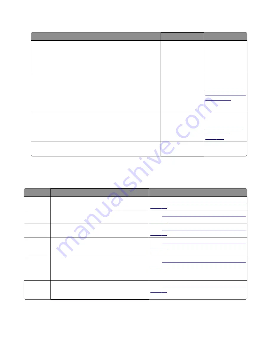
202 paper jams
202 paper jam messages
Error code
Description
Action
202.01
Exit sensor is covered during warm up.
Go to
“Sensor (fuser exit) jam service check” on
202.03
Media did not reach the fuser exit sensor.
“Sensor (fuser exit) jam service check” on
202.05
Exit sensor covered too long or exit sensor did not
clear ahead of a sheet.
“Sensor (fuser exit) jam service check” on
202.13
Restart attempted after an internal jam without
cover open. Close event. Likely that the jam was
not actually cleared.
“Sensor (fuser exit) jam service check” on
202.14
Expected banner sheet ( assumed wide ) not
detected by narrow media sensor, possible
accordion jam, unsupported narrow banner
media, or missing signal.
“Sensor (fuser exit) jam service check” on
202.16
Page at fuser nip before fuser started ramping
toward desired. Indicates code may be receiving
more hall interrupts than intended.
“Sensor (fuser exit) jam service check” on
4514-6xx
Diagnostics and troubleshooting
96
Summary of Contents for M3150
Page 12: ...Part name index 393 4514 6xx Table of contents 12 ...
Page 20: ...4514 6xx 20 ...
Page 38: ...4514 6xx 38 ...
Page 172: ...4514 6xx 172 ...
Page 246: ...3 Remove two screws A and then remove the cooling fan mount A 4514 6xx Parts removal 246 ...
Page 256: ...5 Remove the four screws B and then remove the right front mount B 4514 6xx Parts removal 256 ...
Page 260: ...b Set the spring over the plunger 4514 6xx Parts removal 260 ...
Page 277: ...3 Squeeze the latches B to release the left and right links B 4514 6xx Parts removal 277 ...
Page 300: ...3 Place the printer on its rear side 4 Release the sensor flag A 4514 6xx Parts removal 300 ...
Page 301: ...5 Remove the screw B 6 Remove the sensor flag bracket C 4514 6xx Parts removal 301 ...
Page 323: ...3 Swing the right cover backward to remove 4 Remove the screw D 4514 6xx Parts removal 323 ...
Page 333: ...4514 6xx 333 ...
Page 335: ...Assembly 1 Covers 4514 6xx Parts catalog 335 ...
Page 338: ...4514 6xx Parts catalog 338 ...
Page 339: ...Assembly 2 Electronics 1 1 2 3 4 5 7 9 10 11 6 8 12 4514 6xx Parts catalog 339 ...
Page 342: ...4514 6xx Parts catalog 342 ...
Page 343: ...Assembly 3 Electronics 2 4 3 2 1 5 6 8 9 7 4514 6xx Parts catalog 343 ...
Page 345: ...4514 6xx Parts catalog 345 ...
Page 346: ...Assembly 4 Frame 10 11 12 13 14 9 1 5 6 7 8 4 4 2 3 4514 6xx Parts catalog 346 ...
Page 349: ...Assembly 5 Option trays 3 4 5 6 1 2 4514 6xx Parts catalog 349 ...
Page 354: ...4514 6xx Parts catalog 354 ...
Page 356: ...4514 6xx Parts catalog 356 ...
Page 364: ...4514 6xx 364 ...
Page 376: ...4514 6xx 376 ...
Page 386: ...4514 6xx Index 386 ...
Page 392: ...4514 6xx Part number index 392 ...
Page 398: ...4514 6xx Part name index 398 ...


