background image

4080-001

Lexmark Optra™ Color 45

Lexmark and Lexmark with diamond
design are trademarks of Lexmark
International, Inc., registered in the
United States and/or other countries.

• Table of Contents

• Index

• Safety and Notices

• Trademarks

• Start Diagnostics

Summary of Contents for Optra Color 45

Page 1: ...ra Color 45 Lexmark and Lexmark with diamond design are trademarks of Lexmark International Inc registered in the United States and or other countries Table of Contents Index Safety and Notices Trademarks Start Diagnostics ...

Page 2: ...artment D22 035 3 740 New Circle Road N W Lexington Kentucky 40550 U S A Lexmark may use or distribute any of the information you supply in any way it believes appropriate without incurring any obligation to you You can purchase additional copies of publications related to this product by calling 1 800 553 9727 In other countries contact your point of purchase Lexmark and Optra are trademarks of L...

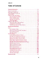
Page 3: ...tor Table 2 2 Power On Self Test POST Sequence 2 4 Post Symptom Table 2 5 Symptom Tables 2 6 Service Checks 2 9 Controller Board Service Check 2 9 Encoder Card Strip Service Check 2 9 End of Forms EOF Service Check 2 10 Maintenance Station Service Check 2 10 Noisy Paper Feed Motor Service Check 2 11 Operator Panel Buttons Service Check 2 11 Operator Panel LCD Display Service Check 2 12 Options Ser...

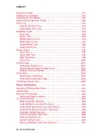
Page 4: ...tup 3 11 Setting the Page Count 3 11 Viewing the Permanent Page Count 3 11 Restore Factory Defaults 3 12 Print Tests 3 12 Print Quality Test Page 3 13 Printing Menu Settings Page 3 14 Test Page Quick Test 3 15 Repair Information 4 1 Handling ESD Sensitive Parts 4 1 Adjustments 4 2 Removal Procedures 4 2 Releasing Plastic Latches 4 2 Covers and Doors 4 3 Base Assembly Removal 4 4 Code SIMM Access D...

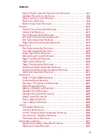
Page 5: ...6 Paper Lifters Removal 4 16 Paper Tray Assembly Removal 4 17 Small Feed Roller Assembly Removal 4 17 Small Feed Roller Holder Assembly Removal 4 17 Star Roller Assembly Removal 4 17 Electronics 4 18 Code or Flash SIMM Removal 4 19 Controller Board Removal 4 20 Encoder Thermistor Card Removal 4 21 Engine Board Removal 4 22 Memory SIMM Card Removal 4 22 Operator Panel Removal 4 24 Operator Panel Ca...

Page 6: ...e 6 1 Lubrication Specifications 6 1 Parts Catalog 7 1 How To Use The Parts Catalog 7 1 Assembly 1 Covers 7 2 Assembly 2 Frames 7 4 Assembly 3 Paper Feed 7 6 Assembly 4 Electronics 7 8 Assembly 5 Carrier 7 10 Assembly 6 Carrier Transport 7 12 Assembly 7 Maintenance Station 7 14 Assembly 8 Options 7 16 Index I 1 ...

Page 7: ... of this product Professional service personnel should understand this and take necessary precautions Consignes de Sécurité Ce produit a été conçu testé et approuvé pour respecter les normes strictes de sécurité globale lors de l utilisation de composants Lexmark spécifiques Les caractéristiques de sécurité de certains éléments ne sont pas toujours évidentes Lexmark ne peut être tenu responsable d...

Page 8: ...ersonale di assistenza autorizzato deve quindi adottare le precauzioni necessarie Sicherheitshinweise Dieses Produkt und die zugehörigen Komponenten wurden entworfen und getestet um beim Einsatz die weltweit gültigen Sicherheitsanforderungen zu erfüllen Die sicherheitsrelevanten Funktionen der Bauteile und Optionen sind nicht immer offensichtlich Sofern Teile eingesetzt werden die nicht von Lexmar...

Page 9: ... la máquina El personal cualificado debe ser consciente de este peligro y tomar las precauciones necesarias Informações de Segurança Este produto foi concebido testado e aprovado para satisfazer os padrões globais de segurança na utilização de componentes específicos da Lexmark As funções de segurança de alguns dos componentes podem não ser sempre óbvias A Lexmark não é responsável pela utilização...

Page 10: ... algunes peces pot ser que no sempre siguin òbvies Lexmark no es responsabilitza de l us d altres peces de recanvi La informació pel manteniment d aquest producte està orientada exclusivament a professionals i no està destinada a ningú que no ho sigui El risc de xoc elèctric i de danys personals pot augmentar durant el procés de desmuntatge i de servei d aquest producte El personal professional ha...

Page 11: ...xi 4080 001 ...

Page 12: ...xii Service Manual 4080 001 ...

Page 13: ...nting average Maintenance Approach The diagnostic information in this manual leads you to the correct field replaceable unit FRU or part Use the error indicator charts symptom index service checks and diagnostic aids to determine the symptom and repair the failure This printer can be serviced without being connected to a host computer The user is directed in the Printer Control program to perform ...

Page 14: ... of Forms ESD Electrostatic Discharge FRU Field Replaceable Unit LED Light Emitting Diode POST Power On Self Test SIMM Single In line Memory Module RAM Random Access Memory ROM Read Only Memory V ac Volts alternating current V dc Volts direct current ...

Page 15: ...by 16 character liquid crystal display LCD five buttons and one indicator light Printer Indicator Light The printer indicator light gives information about the status of your printer Light State Meaning On solid Powered On and in the Ready state Flashing Powered On and Busy Off Unplugged from the power source Operator Panel Display Printer Indicator Light ...

Page 16: ...eady for jobs to print Menu and Menu Each end of the button has a function Press the Menu or Menu button At the Ready message to take the printer offline out of the Ready state and enter the menus At the Busy message to take the printer to the JOB MENU When the printer is offline Press Menu to go to the next item in the menus or Press Menu to go to the previous item in the menus For menu items tha...

Page 17: ...ng When the Ready status message displays the printer is ready to receive a print job While a job is printing the Busy status message appears on the first line of the operator panel display Return Press the Return button to return to the previous menu level Stop Press the Stop button At the Ready Busy or Waiting message to temporarily stop all activity and take the printer offline The printer oper...

Page 18: ...unction when you use the specified printer language An asterisk next to a value indicates the original factory default setting and may vary for different countries When you select a new setting from the operator panel the asterisk moves next to the selected setting to identify it as the current user default These settings are active until new ones are stored or the factory defaults are restored Ch...

Page 19: ... Ready status message appears on the display 2 Press Menu or Menu to enter the menus 3 Continue to press and release Menu until you see Tests Menu 4 Press Select Tests Menu appears on the first line and Print Menus is on the second line 5 Press Select to select Print Menus The message Printing Menu Settings appears and remains on the operator panel display until the page prints The printer returns...

Page 20: ... Some menu items have sub menus You must select another menu such as Tray 1 Type before the available values display 6 Press Menu or Menu until the value you need appears on the second line of the display 7 Press Select An asterisk appears beside the value to indicate that it is now the user default setting The display shows the new setting for one second and then clears The Saved message displays...

Page 21: ... cannot be made to the printer default settings 1 Unplug the printer 2 While pressing Go and Stop plug in the printer 3 Release the buttons when Performing Self Test displays When the printer self test completes the Ready status message appears If you press Menu or Menu the Menus Disabled message displays ...

Page 22: ...1 10 Service Manual 4080 001 ...

Page 23: ...checks and diagnostic aids to determine the printer failure Start Service error indications are displayed on the operator panel If your printer displays an error indication locate the error number in the Error Indicator Table on page 2 2 and take the indicated action Unplug the printer to clear the error indicator ...

Page 24: ...eplace the controller board refer to the Controller Board Service Check on page 2 9 If the problem remains replace the engine board refer to the Engine Board Removal on page 4 22 Note The controller software can cause a 939 error 941 RIP code CRC Refer to the Controller Board Service Check on page 2 9 943 RIP font version Replace Font SIMM 944 945 946 Processor failure ASIC failure SRAM failure Re...

Page 25: ...ncorrect card is installed replace the card 976 977 Unrecoverable software error in network card Communication error with network card Go to the Options Service Check on page 2 13 If the problem remains replace the controller card 978 979 Network card checksum error Flash Network card error Replace network card Error Symptom Action ...

Page 26: ...the operator panel display and then turns off 4 The carrier moves to the center of the frame and returns to the maintenance station 5 The paper feed motor turns 6 The printer indicator light turns off and then back on 7 Ready is displayed indicating that POST is complete If your printer completes POST with no errors go to the Symptom Tables on page 2 6 locate the symptom and take the indicated act...

Page 27: ...on page 2 15 Transport motor does not turn Go to the Transport Service Check on page 2 24 Carrier drives into left side frame Go to the Transport Service Check on page 2 24 Printer indicator light does not light or remains on Go to the Operator Panel LCD Display Service Check on page 2 12 POST incomplete printer indicator light on no motors turn and Performing Self Test is displayed Go to the Powe...

Page 28: ... No carrier movement Slow carrier movement Carrier stops Carrier strikes left side frame Go to the Transport Service Check on page 2 24 Go to the Transport Service Check II on page 2 25 Symptom Action Printer not communicating with host computer Go to the Parallel Wrap Test on page 3 6 Symptom Action Fails to cap the printhead Fails to clean the printhead Go to the Maintenance Station Service Chec...

Page 29: ...ge 2 11 All diamonds on display Go to the Operator Panel LCD Display Service Check on page 2 12 Symptom Action Paper fails to stop at first print line Fails to pick paper Picks more than one sheet of paper Picks paper but fails to feed Paper jams Paper fails to exit Noisy paper feed Paper skews Go to the Paper Feed Service Check on page 2 15 Paper does not feed motor does not turn Go to the Paper ...

Page 30: ...on Voids in characters Light print Prints off the page Fuzzy print Carrier moves but does not print Printhead drying prematurely Vertical alignment off Excessive ink flow Flooding Horizontal banding Go to the Print Quality Service Check on page 2 21 Ink smearing Vertical streaks on paper Print lines crowded Go to the Paper Feed Service Check on page 2 15 ...

Page 31: ...ck to the maintenance station Ready should appear on the display If not check the connection at the encoder card CN1 and retest If the problem remains replace the encoder card refer to the Encoder Thermistor Card Removal on page 4 21 You may have to perform this check several times FRU Action 1 Code SIMM Some printers may contain a code SIMM located in the option card s J6 on the controller board ...

Page 32: ...aintenance Station Assembly As the carrier moves to the right over the maintenance station a slot on the bottom of the carrier engages a tab on the sled of the maintenance station causing the caps to rise and seal the printheads Carrier movement to the left will uncap the printheads The wipers clean the printhead nozzles as the carrier leaves the maintenance station The wipers clean the printheads...

Page 33: ... Feed Motor Removal on page 4 16 2 Gears Check the gears for proper alignment chipped teeth loose motor missing gear clip or worn gears FRU Action 1 Operator Panel Assembly If any button fails the button test replace the operator panel assembly 2 Controller Board Operator Panel Assembly Be sure the voltage at JT6 2 measures 5 V dc If the voltage is incorrect replace the controller board If the vol...

Page 34: ...er Board Verify the voltage at JT6 2 on the controller board is approximately 5 V dc If incorrect replace the controller board If correct go to step 2 2 Operator Panel Assembly Verify that the resistance between JT6 4 and ground on the controller board is approximately 0 ohms If incorrect replace the controller board If correct replace the operator panel assembly FRU Action 1 Controller Board Oper...

Page 35: ... damaged If the test fails replace the DRAM SIMM refer to the Memory SIMM Card Cover Removal on page 4 7 If the problem continues replace the controller board refer to the Controller Board Removal on page 4 20 Hard Disk Option Be sure the hard disk and the hard disk adapter board are correctly installed Run the Quick Disk Test on page 3 8 from the Device Test on the Diagnostic Menu when a problem ...

Page 36: ...k card is correctly installed in the controller board socket and is properly grounded If you find no problem contact your next level of support before replacing the network card Error Code 977 Network Card A 977 error displays when the RIP software detects that a network card is installed but cannot establish communications with the network card Replace the network card refer to Option Card s Remo...

Page 37: ...per is being used Check for static in the paper Ensure the correct position of the left paper adjuster guide lifter assembly Check for skew by performing the Test Page Quick Test on page 3 15 FRU Action 1 Gears Check for binds in the gear train and paper feed mechanism by rotating the large feed roll by hand Check all gears for correct installation and signs of wear or damage If there is a bind is...

Page 38: ...ly 12 5 ohms If incorrect replace the paper feed motor assembly If correct check the continuity between each motor pin on the motor connector and the motor case If continuity exists replace the paper feed motor assembly If the symptom remains go to step 3 Note If a short exists in the paper feed motor damage to the system board drivers and power supply may occur 3 Power Supply Disconnect the AC li...

Page 39: ...ction If when paper is fed from the input tray and the motor turns in one direction only replace the engine board FRU Action 1 Gear Box Check the clutch lever for obstructions and the gear box for binds and wear Replace worn or binding gears 2 Gears Check for binds in the gear train and paper feed mechanism by rotating the large feed roll by hand If you notice a bind isolate it by removing one of ...

Page 40: ...perly Be sure the correct type of paper is being used Be sure the printer is installed on a flat surface FRU Action 1 Large and Small Feed Rollers Check for wear and binds 2 Small Feed Roller Springs Check for damage 3 Exit Roller Star Rollers Check for wear and binds 4 Input Output Tray Check the following for wear or damage Paper lifters assemblies All parts inside the left and right edge guides...

Page 41: ...e is defective replace the fuse and re verify the voltage at J2 1 If incorrect continue to step 4 Note Disconnect the line cord prior to checking fuse F1 4 Power Supply If fuse F1 continues to fail replace the fuse and disconnect the J2 connector from the controller board before applying power Check for approximately 5 V dc between connector J2 1 and ground If incorrect replace the power supply If...

Page 42: ...ard If correct disconnect the motor and check the resistance between CN5 1 and CN5 2 which should measure between 10 5 12 5 ohms If the resistance is incorrect replace the motor If the resistance is correct check for approximately 30 V dc on the transistor tab Q17 on the engine board If the voltage is incorrect replace the engine board If the voltage is correct go to step 3 3 Controller Board Cabl...

Page 43: ...on Set print quality to normal and be sure the correct paper type is selected in the paper menu Set the color menu to Vivid and select black and white if checking B W print quality FRU Action 1 Printhead Carrier Assembly Re seat the printhead cables in the engine board and check the following parts for wear or damage Print Cartridge Latch Latch Spring Carrier ...

Page 44: ... may need to remove the cable from the carrier to inspect it A worn rubber backer results in poor contact between the printhead cable and the print cartridge Check the rubber backer for wear Refer to the test page The temperature value is Celsius Note Printing slows to prevent overheating and excessive ink flow when the temperature is above the normal operating range or when printing complex graph...

Page 45: ...area Check the following Transport belt for wear and full engagement into the carrier grip Carrier guide rod for wear or dirt Carrier to carrier frame engagement should be lubricated with grease P N 99A0394 Lubricate the carrier guide rod and carrier frame on both sides where the two surfaces ride on the frame Idler pulley parts for wear damage or looseness Encoder strip for wear or dirt 6 Alignme...

Page 46: ...ngine board 2 Engine Board Disconnect CN5 from the engine board and check for approximately 30 V dc between CN5 1 and ground If incorrect replace the engine board 3 Carrier Guide Rod Clean the carrier rod Note Lubricate the rod and the carrier rod bearing surface 4 Carrier Belt Idler Pulley Parts Carrier Frame Check for worn loose or broken parts Check for obstructions blocking carrier movement 5 ...

Page 47: ...ck to where it is parked over the maintenance station After several seconds Ready should appear on the display If not check the connection at the encoder card CN1 and retest If the problem remains replace the encoder card Tray 2 Service Check Note Be sure the tray 2 is properly installed and loaded Paper does not feed FRU Action 1 Drive Gear Check for binds and any obstructions in the paper path 2...

Page 48: ...Autocompensator Check the autocompensator and clutch spring Be sure the roller on the autocompensator turns when paper is fed If the roller fails to turn be sure the drive belt is installed properly If the problem remains replace the paper tray 2 FRU Action 1 Gears Be sure the tray 2 drive gear and clip are installed properly 2 Tray 2 Drive Gear Be sure the drive gear clips are properly installed ...

Page 49: ...ata in RAM Simplifying your print job Installing additional memory Press Menu or Menu to access the reset function in the Busy Waiting Menu group Menu Lockout does not prevent access to the Busy Waiting Menu group The menu buttons are not active when Reset Control is Off 51 Defective Flash Press Go to clear the message and continue processing the job All downloaded fonts and macros not written to ...

Page 50: ...he serial interface parameters protocol baud parity and data bits are set correctly on the printer and the host computer If a parallel error has occurred check the cable connection between the host and printer Press Menu or Menu to access the reset function in the Busy Waiting Menu group Menu Lockout does not prevent access to the Busy Waiting Menu group The menu buttons are not active when Reset ...

Page 51: ... does not prevent access to the Busy Waiting Menu group 56 Parallel Port Disabled Once the error has been displayed for the first time reporting of further error is suppressed until the menus are entered or the printer is reset Press Go to clear the message The printer discards any data received on the serial port Enable the serial port Press Menu or Menu to access the reset function in the Busy W...

Page 52: ... not active when Reset Control is Off Note Menu Lockout does not prevent access to the Busy Waiting Menu group 63 Unformatted Disk Press Go to clear the message The disk will be marked as bad and normal operation continues Disk operations are not allowed until the disk is formatted 200 Paper Jam This message indicates that a paper jam has occurred If the error does not clear after cleaning the pap...

Page 53: ...Go and Return buttons 3 Turn the printer on 4 Release the buttons when Performing Self Test displays on the operator panel Note Select Exit Diagnostics to return to normal mode The tests display on the operator panel in the order shown Print Tests Hardware Tests Printer Setup Error Log Align Cartridges Base Sensor Tests Exit Diagnostics ...

Page 54: ...ign Page 8 Use the test page to check each alignment A D 9 If changes are necessary repeat step 5 Cleaning the Printheads 1 Enter Diagnostics Mode 2 Select Hardware Test 3 Press MENU to go to Clean Heads 4 Press Select The nozzle test pattern test page prints Paper Lifters Operation Theory As the carrier applies pressure against the clutch lever located in the gear box assembly the left and right ...

Page 55: ...itions in the log are entered All 2xx and 9xx error messages are stored in the error log To view the Error Log 1 Select Display Log from the Error Log menu The Error log displays on 3 screens as only 4 entries display at a time 2 To move to the next screen press Menu to move forward or Menu to move backward 3 Press Return Stop to exit the Error Log Clearing the Error Log To clear the Error Log 1 S...

Page 56: ...st 1 Select LCD Test from the Diagnostic menu The LCD test continually executes the LCD display test 2 Press Return Stop to cancel the test Button Test To run the Button Test 1 Select Button Test from the Diagnostic menu With no buttons pressed several OP Open appear on the display 2 Press each button one at a time and a CL Closed displays in place of an OP The proper operation of each button can ...

Page 57: ...urn Stop to exit the test P represents the number of times the memory test has passed and finished successfully Initially 000000 displays with the maximum pass count being 999 999 F represents the of time the memory test has failed and finished with errors Initially 00000 displays with the maximum fail count being 99 999 Once the maximum pass count or fail count is reached the test is stopped the ...

Page 58: ...il count is reached the test stops with the power indicator on solid The final results display on the screen Parallel Wrap Test This test is used with a wrap plug to check operation of the parallel port hardware Each parallel signal is tested To run the Parallel Wrap Test 1 Disconnect the parallel interface cable and install the wrap plug P N 1319128 2 Select the Parallel Wrap Test from the menu T...

Page 59: ...The power indicator blinks indicating the test is running 3 This test runs continuously unless canceled by pressing Return Stop Each time the test finishes the screen updates with the result If the test passes the Pass Count increases by 1 however if the test fails a message displays for approximately 3 seconds and the Fail Count increases by 1 Once the maximum count is reached the test stops The ...

Page 60: ... block per track on the disk The test reads one block on each track saves the data and proceeds to write and read four test patterns to the bytes in the block If the block is good the saved data is written back to the disk To run the Quick Disk Test 1 Select the Quick Disk Test from the Device Tests menu The power indicator blinks while the test is in progress Quick Disk Test Test Passed message d...

Page 61: ...k Test Clean BAD 000000 00 message displays The screen updates periodically indicating the percentage of test completed and the number of bad blocks found 3 The power indicator blinks during the test The test can be canceled anytime during the test by pressing Return Stop Once the test is complete the power indicator shows solid and a message displays XXXX Bad Blocks YYYYYY Usable message displays...

Page 62: ...rmatted at the end of the test To run the Flash Test 1 Select Flash Test from the Device Tests menu The power indicator blinks while the test is running Flash Test Test Passed message displays if the test passes and the power indicator shows solid Flash Test Test Failed message displays if the test fails and the power indicator shows solid 2 Press Go or Return Stop to return to the Device Tests me...

Page 63: ...isplays b The leftmost digit blinks indicating it is the first digit to be changed 3 Press either Menu or Menu until the value you want displays 4 Press Select to move to the next digit press Menu or Menu until the value you want displays Continue with each digit until you set the page count You can skip any digit by pressing Select 5 Press Select to save the new page count in NVRAM 6 Press Return...

Page 64: ...in the following order in the menu Tray 1 input tray Optional Paper Tray 2 if installed Manual Tray For each input source selected you have the following choice Single prints the Quick Test Page once Continuous continue printing the Quick Test Page until Return or Stop is pressed The contents of the Quick Test Page varies depending on the media installed in the selected input source To run the Pri...

Page 65: ...rinter 4 Release the buttons once Performing the Self Test displays 5 The printer performs its normal POR cycle then prints one copy of the Print Quality Test page If you want more than one copy perform these steps again The following is printed on page 1 Contents of the Diagnostic Error Log Printer configuration information printer serial number controller code level engine code level operator pa...

Page 66: ...tains the following information A list of all the printer settings contained in the control panel menus and their values A list of the installed options and features such as RAM memory SIMMs optional input paper trays flash or disk Printer information such as serial number page count installed RAM engine code level RIP code level control panel code levels font ROM version SRAM availability supplie...

Page 67: ...side To check the color run Hardware Tests clean heads To run the test 1 Select Print Tests from the Diagnostic menu 2 Select Tray 1 or optional Tray 2 3 Select Single or Continuous If single is selected no buttons are active during printing If continuous is selected Return or Stop can be selected to cancel the test 4 Check the test page from each source to assist in print quality and paper feed p...

Page 68: ...3 16 Service Manual 4080 001 ...

Page 69: ...rpets and furniture Put the ESD wrist strap on your wrist Connect the wrist band to the system ground point This discharges any static electricity in your body to the printer Hold the ESD sensitive part by its edge connector shroud cover do not touch its pins If you are removing a pluggable module use the correct tool Do not place the ESD sensitive part on the printer cover or on a metal table if ...

Page 70: ...tridge Removal Procedures The following procedures are arranged according to the name of the printer part discussed Unplug the power cord before removing any parts Releasing Plastic Latches Many of the parts are held in place with plastic latches The latches break easily release them carefully To remove such parts press the hook end of the latch away from the part to which it is latched ...

Page 71: ...Repair Information 4 3 4080 001 Covers and Doors ...

Page 72: ...s cover refer to Controller Board Access Cover Removal on page 4 5 6 Disconnect the operator panel connector and the engine board connector from the contoller board 7 Remove the four screws from the controller board and remove the board 8 Remove the operator panel cable and the engine board cable Note the routing of the cables 9 Remove the power supply refer to the Power Supply Removal on page 4 2...

Page 73: ...de the carrier frame assembly toward the rear lift up and remove it from the base 7 Remove the two screws from the controller board access cover and remove Controller Board Access Door Removal 1 Remove the input output tray assembly 2 Open the front access door refer to Covers and Doors on page 4 3 3 Remove the paper tray refer to the Paper Tray Assembly Removal on page 4 17 4 Depress the clip on ...

Page 74: ... assembly 2 Remove the two screws from the front cover located on the bottom of the printer Refer to Covers and Doors on page 4 3 3 Release the latch beside each screw from the front cover and pull forward off the base 4 Disconnect the operator panel cable and note the routing Note Do not turn the printer on its back as this may cause the ink to spill Gutter Pad Removal 1 Remove the input output t...

Page 75: ...astic Controller Board Cover Removal 1 Remove the optional card s cover refer to Covers and Doors on page 4 3 2 Facing the rear of the printer remove the two screws securing the metal controller plate to the plastic controller board and remove the plate 3 Remove the three screws holding the plastic controller board and remove the board Note When reinstalling the metal plate be sure the arrow point...

Page 76: ...over Removal Depress the option card s cover and slide it to the rear of the printer to remove Refer to the Covers and Doors on page 4 3 Rear Cover Removal 1 Remove the input output tray assembly 2 Remove the front cover refer to the Front Cover Removal on page 4 6 3 Disconnect the operator panel cable and note the routing 4 Remove the metal and plastic controller board covers refer to the Metal P...

Page 77: ...Repair Information 4 9 4080 001 Rear Access Cover Removal 1 Turn the printer around so the back is facing you 2 Depress the tabs located at the top of the rear access door cover and remove ...

Page 78: ...4 10 Service Manual 4080 001 Frames ...

Page 79: ...sembly toward the rear lift up and remove it from the base 8 Remove the maintenance station refer to the Maintenance Station Assembly Removal on page 4 32 9 Disconnect the five small feed roller springs from the small feed roller spring connector rail 10 Remove the two screws securing the carrier frame to the left and right side frames 11 Tilt the top of the carrier frame assembly toward the front...

Page 80: ...printer Left Side Frame Assembly Removal 1 Remove the input output tray assembly 2 Remove all covers refer to Covers and Doors on page 4 3 3 Remove the carrier frame assembly refer to the Carrier Frame Assembly Removal on page 4 11 4 Remove the two screws securing the small feed roller spring connector rail and remove the rail refer to Frames on page 4 10 5 Remove the two screws securing the star ...

Page 81: ...13 Right Side Frame Assembly Removal 1 Remove the input output tray assembly 2 Remove all covers refer to Covers and Doors on page 4 3 3 Remove the carrier frame assembly refer to the Carrier Frame Assembly Removal on page 4 11 4 Remove the two screws securing the small feed roller spring connector rail and remove the rail Refer to Frames on page 4 10 5 Remove the two screws securing the star roll...

Page 82: ...4 14 Service Manual 4080 001 Paper Feed ...

Page 83: ... plastic clip on the clutch lever at the end of the large feed roller shaft and remove the clutch lever Be sure the grove on the clutch lever aligns with the clutch spring 5 Remove the two screws securing the gear box assembly to the frame 6 Depress the gear box clip on the bottom of the left side frame and remove the gear box assembly and shaft Large Feed Roller Removal 1 Remove the input output ...

Page 84: ...feed motor cable from the controller board at CN6 4 Remove the two screws from the left frame and remove the paper feed motor refer to Frames on page 4 10 Paper Lifters Removal 1 Remove the input output tray assembly 2 Remove all covers refer to Covers and Doors on page 4 3 3 Disconnect the operator panel cable and note the routing 4 Remove the gear box assembly refer to the Gear Box Assembly Remo...

Page 85: ... Press down on the small feed rollers to remove refer to the Paper Feed on page 4 14 Small Feed Roller Holder Assembly Removal 1 Remove the input output tray assembly 2 Remove all covers refer to Covers and Doors on page 4 3 3 Remove the carrier frame assembly refer to the Carrier Frame Assembly Removal on page 4 11 4 Press down on the small feed rollers to remove refer to the Paper Feed on page 4...

Page 86: ...4 18 Service Manual 4080 001 Electronics ...

Page 87: ...the input output tray assembly 2 Turn the printer around so the back is facing you 3 Disconnect the printer power cord and disconnect all cables from the back of the printer 4 Press down on the two tabs located at the top of the rear access door and remove 5 Pull the tab on the code SIMM access door until it rotates toward you 6 Remove the Code SIMM refer to the Memory SIMM Card Removal on page 4 ...

Page 88: ... 22 7 Remove the screw which secures the RIP bracket to the INA bracket located under the printer 8 Remove the two screws securing the controller board access cover and remove the cover 9 Remove the metal plastic controller board covers refer to the Metal Plastic Controller Board Cover Removal on page 4 7 10 Remove the rear access door refer to the Covers and Doors on page 4 3 11 Open the code SIM...

Page 89: ... from the engine board 5 Remove the carrier shaft retainer clip from the right side of the carrier shaft 6 Remove the screw from the left side of the carrier shaft 7 Remove the carrier shaft by sliding it to the right 8 Gently lift up on the carrier taking care not to damage the encoder strip and disconnect the carrier belt 9 Disconnect the printhead cable from the encoder thermistor card 10 Remov...

Page 90: ...CN10 5 Disconnect the transport carrier motor cable from the engine board at location CN5 and the paper feed motor cable at location CN6 and the tray 2 connector CN11 6 Remove the two screws from the engine board and remove the engine board Note Take care with the routing of the paper feed motor cable Pull the EOF flag out of the sensor while removing the engine board Memory SIMM Card Removal 1 Re...

Page 91: ...emove the memory SIMM card cover refer to Memory SIMM Card Cover Removal on page 4 7 4 Remove the memory SIMM card by pushing the metal clips at both ends of the connector outward and lifting the memory SIMM card up and out of the printer ...

Page 92: ...il it snaps into place 3 Be sure both metal clips on the connector are fastened and the two pins on each end are pushed through the holes on the memory SIMM card Operator Panel Removal 1 Remove the input output tray assembly 2 Remove the front cover refer to Covers and Doors on page 4 3 3 Disconnect the operator panel cable and note the routing 4 Remove the four screws securing the operator panel ...

Page 93: ...emove the carrier frame refer to the Carrier Frame Assembly Removal on page 4 11 5 Remove the controller board cover refer to the Controller Board Removal on page 4 20 6 Disconnect the operator panel cable from the controller board Option Card s Removal 1 Remove the option card cover refer to Covers and Doors on page 4 3 2 Remove the two screws securing the optional card 3 Gently pull the option c...

Page 94: ... side of the power supply 5 Remove the ground screw from behind the J2 connector on the controller card 6 Depress the clips on both sides of the power supply and slide the power supply out of the machine Note When replacing the power supply be sure the metal tab on the left side of the power supply is inserted under the controller board Tray 2 Sensor Removal 1 Remove the input output tray assembly...

Page 95: ...Repair Information 4 27 4080 001 Carrier ...

Page 96: ...ainer clip from the right side of the carrier shaft 6 Remove the screw from the left side of the carrier shaft 7 Remove the carrier shaft by sliding it to the right 8 Gently lift up on the carrier taking care not to damage the encoder strip and remove the carrier 9 Push the idler pulley to the right to release the tension on the belt and remove the belt Note When reinstalling the carrier belt take...

Page 97: ... 6 Remove the two screws securing the carrier transport motor to the carrier frame and remove the motor Note the routing of the motor cable Encoder Strip Retainer Removal 1 Remove the input output tray assembly 2 Remove the front cover refer to Covers and Doors on page 4 3 3 Gently release the tension on the encoder strip by flexing the encoder strip tensioner and remove the encoder strip 4 Remove...

Page 98: ...the carrier assembly to the right side of the printer 5 Remove the carrier shaft retainer clip from the right side of the carrier shaft 6 Remove the screw from the left side of the carrier shaft 7 Remove the carrier shaft by sliding it to the right 8 Gently lift up on the printhead carrier disconnect the carrier belt and remove the carrier Note When reinstalling the carrier belt take care not to d...

Page 99: ...Repair Information 4 31 4080 001 Maintenance Station ...

Page 100: ...screws at the rear of the maintenance station and remove the maintenance station Wipers and Caps Removal 1 Remove the input output tray assembly 2 Remove all covers refer to Covers and Doors on page 4 3 3 Remove the maintenance station assembly refer to the Maintenance Station Assembly Removal on page 4 32 4 Remove the wipers and caps Note Be sure the wipers are completely seated ...

Page 101: ...1 5 Connector Locations Engine Board CN2 Printhead Cable 1 CN3 Printhead Cable 2 CN4 Printhead Cable 3 CN5 Transport Motor CN6 Paper Feed Motor CN10 Controller Board Cable PH1 EOF Sensor CN11 Optional Tray 2 Sensor Q17 Transistor Tab ...

Page 102: ...5 2 Service Manual 4080 001 Controller Board J1 Engine Board J2 Power Supply J3 Parallel Port J5 Flash SIMM J6 Code SIMM J7 Memory SIMM J8 INA Option JT6 Operator Panel ...

Page 103: ...to prevent problems and maintain optimum performance Lubrication Specifications Lubricate only when parts are replaced or as needed not on a scheduled basis Use grease P N 99A0394 to lubricate the following All gear mounting studs The ends of the large feed roller at the side frames The carrier rail and shaft Both ends of the exit roller shaft ...

Page 104: ...6 2 Service Manual 4080 001 ...

Page 105: ...Catalog How To Use The Parts Catalog NS Not Shown in the Asm Index column indicates that the part is procurable but is not shown in the illustration PP in the Description column indicates the part is available in the listed parts packet ...

Page 106: ...7 2 Service Manual 4080 001 Assembly 1 Covers ...

Page 107: ...0639 1 Operator Panel 7 99A0620 1 Cover Front 8 99A0625 1 Cover Controller Board Access 9 99A0763 1 Pad Gutter 10 99A0638 1 Cover Option Card s 11 99A0618 1 Base Asm 12 99A0641 1 Envelope Guide 13 99A0619 1 Tray Input Output 14 99A0760 1 Cover Memory SIMM Card 15 99A0621 1 Cover Operator Panel 16 99A0622 1 Door Front Access NS 99A0640 1 Operator Panel Overlay Kit NS 99A0758 1 Springs PP NS 99A0642...

Page 108: ...7 4 Service Manual 4080 001 Assembly 2 Frames ...

Page 109: ...4 1 Rail Carrier 2 99A0737 1 Rail Small Feed Roller Spring Connector 3 99A0643 1 Frame Carrier Asm 4 99A0732 1 Frame Mid 5 99A0738 1 Roller Star Asm 6 99A0761 1 Bearings PP 7 99A0648 1 Frame Right Side Asm 8 99A0694 1 Frame Left Side Asm 9 99A0759 1 Gears PP 10 99A0743 1 Pulley Idler Tension Asm ...

Page 110: ...7 6 Service Manual 4080 001 Assembly 3 Paper Feed ...

Page 111: ...sm 3 99A0735 1 Roller Large Feed Asm with Gear 4 99A0738 1 Roller Star Asm 5 99A0729 1 Sheet Feeder Manual 6 99A0728 1 Roller Exit Asm 7 99A0649 1 Paper Lifter Right 8 99A0730 1 Tray Paper 9 99A0731 1 Shaft Hinge 10 99A0727 1 Paper Lifter Left 11 99A0759 1 Gears PP 12 99A0739 1 Motor Paper Feed Asm with Gear 13 99A0741 1 Box Gear Asm 14 99A0758 1 Spring Clutch PP ...

Page 112: ...7 8 Service Manual 4080 001 Assembly 4 Electronics ...

Page 113: ...4 1 Board Controller 7 99A0753 1 Cable Controller Board 8 99A0639 1 Panel Operator 9 99A0752 1 Cable Operator Panel NS 1339518 1 Cord Power Australia NS 1339518 1 Cord Power New Zealand NS 1339525 1 Cord Power Denmark NS 1339520 1 Cord Power Europe NS 1339521 1 Cord Power Israel NS 1339524 1 Cord Power Italy NS 1339523 1 Cord Power South Africa NS 1339522 1 Cord Power Switzerland NS 1339519 1 Cord...

Page 114: ...7 10 Service Manual 4080 001 Assembly 5 Carrier ...

Page 115: ...Printhead Asm 2 99A0757 4 Screws PP 3 99A0751 1 Encoder Card w Thermistor 4 99A0734 1 Shaft Carrier 5 99A0758 1 Spring Carrier Shaft PP 6 99A0745 1 Printhead Interlock Key B M 7 99A0761 1 Bearings PP 8 99A0761 1 Clamp Bearings PP NS 13A3860 1 Garage Asm with Sticker NS 99A0647 1 Holder FPC Flat Printhead Cable ...

Page 116: ...7 12 Service Manual 4080 001 Assembly 6 Carrier Transport ...

Page 117: ...dex Part Number Units Description 6 1 99A0742 1 Motor Carrier Transport 2 99A0744 1 Belt Carrier 3 99A0646 1 Strip Encoder 4 99A0757 5 Screw Carrier Transport Motor PP 5 99A0645 1 Retainer Encoder Strip 6 99A0743 1 Pulley Idler Tension Asm 7 99A0644 1 Rail Carrier ...

Page 118: ...7 14 Service Manual 4080 001 Assembly 7 Maintenance Station ...

Page 119: ...Parts Catalog 7 15 4080 001 Assembly 7 Maintenance Station Asm Index Part number Units Description 7 1 99A0755 1 Maintenance Station Asm 2 99A0756 1 Wiper and Cap B M PP ...

Page 120: ...apan DBCS Simm 1 NS 99A0521 1 Card Flash Memory 1MB NS 99A0522 1 Card Flash Memory 2MB NS 99A0523 1 Card Flash Memory 4MB NS 99A0515 1 Disk Hard w o Adapter Card NS 99A0516 1 Card Hard Disk Adapter with Hard Disk NS 99A0420 1 Card Token Ring NS 99A0421 1 Card 10 100 Ethernet NS 99A0422 1 Card 10Base2 10BaseT NS 99A0560 1 Card INA Omnibus NS 99A0467 1 Card Parallel Port 1284C NS 99A0424 1 Adapter I...

Page 121: ...2 Error Messages User 2 27 ESD Sensitive Parts 4 1 L Lubrication Specifications 6 1 M Maintenance Approach 1 1 P Plastic Latches 4 2 POST Sequence 2 4 Power Consumption 1 1 Printer Setup 3 11 Problems Carrier Transport 2 6 Communications 2 6 Dead Machine 2 8 Maintenance Station 2 6 Operator Panel 2 7 Paper Feed 2 7 Print Quality 2 8 R Removals Carrier An Illustration 4 27 Belt 4 28 Encoder Strip 4...

Page 122: ...5 Gear Box Asm 4 15 Large Feed Roller 4 15 Manual Sheet Feeder 4 16 Motor 4 16 Paper Lifters 4 16 Paper Tray Asm 4 17 Small Feed Roller 4 17 Small Roller Holder 4 17 Star Roller Asm 4 17 4 26 Tray 2 Sensor 4 26 Repair Information 4 1 S Service Checks 2 9 Encoder Card 2 9 Encoder Strip 2 9 End of Form EOF 2 10 Maintenance Station 2 10 Operator Panel 2 11 Operator Panel Display 2 12 2 19 Options 2 1...

Reviews: