Repair Information
4-13
4080-001
Mid Frame Assembly Removal
1. Remove the input / output tray assembly.
2. Remove all covers, refer to
“Covers and Doors” on page 4-3
.
3. Remove the carrier frame assembly, refer to the
“Carrier
Frame Assembly Removal” on page 4-11
.
4. Remove the right side frame, refer to the
“Right Side Frame
Assembly Removal” on page 4-13
.
Right Side Frame Assembly Removal
1. Remove the input / output tray assembly.
2. Remove all covers, refer to
“Covers and Doors” on page 4-3
.
3. Remove the carrier frame assembly, refer to the
“Carrier
Frame Assembly Removal” on page 4-11
.
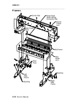
4. Remove the two screws securing the small feed roller spring
connector rail and remove the rail. Refer to
“Frames” on
page 4-10
.
5. Remove the two screws securing the star roller assembly, refer
to the
“Star Roller Assembly Removal” on page 4-17
.
6. Remove the three screws from the right side frame and remove
the frame.
Summary of Contents for Optra Color 45
Page 11: ...xi 4080 001 ...
Page 12: ...xii Service Manual 4080 001 ...
Page 22: ...1 10 Service Manual 4080 001 ...
Page 68: ...3 16 Service Manual 4080 001 ...
Page 71: ...Repair Information 4 3 4080 001 Covers and Doors ...
Page 78: ...4 10 Service Manual 4080 001 Frames ...
Page 82: ...4 14 Service Manual 4080 001 Paper Feed ...
Page 86: ...4 18 Service Manual 4080 001 Electronics ...
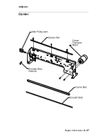
Page 95: ...Repair Information 4 27 4080 001 Carrier ...
Page 99: ...Repair Information 4 31 4080 001 Maintenance Station ...
Page 104: ...6 2 Service Manual 4080 001 ...
Page 106: ...7 2 Service Manual 4080 001 Assembly 1 Covers ...
Page 108: ...7 4 Service Manual 4080 001 Assembly 2 Frames ...
Page 110: ...7 6 Service Manual 4080 001 Assembly 3 Paper Feed ...
Page 112: ...7 8 Service Manual 4080 001 Assembly 4 Electronics ...
Page 114: ...7 10 Service Manual 4080 001 Assembly 5 Carrier ...
Page 116: ...7 12 Service Manual 4080 001 Assembly 6 Carrier Transport ...
Page 118: ...7 14 Service Manual 4080 001 Assembly 7 Maintenance Station ...

