4-22
Service Manual
4080-001
Engine Board Removal
1. Remove the input / output tray assembly.
2. Remove all covers (except the base), refer to
“Covers and
Doors” on page 4-3
.
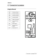
3. Disconnect the three printhead cable connectors from the
engine board.
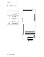
4. Disconnect the controller board cable from the engine card
(CN10).
5. Disconnect the transport carrier motor cable from the engine
board at location (CN5) and the paper feed motor cable at
location (CN6) and the tray 2 connector (CN11).
6. Remove the two screws from the engine board and remove the
engine board.
Note: Take care with the routing of the paper feed motor cable. Pull
the EOF flag out of the sensor while removing the engine board.
Memory (SIMM) Card Removal
1. Remove the input / output tray assembly.
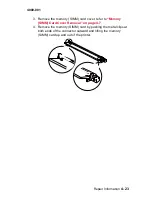
2. Open the front access door, by pulling up on the tab, as shown.
Summary of Contents for Optra Color 45
Page 11: ...xi 4080 001 ...
Page 12: ...xii Service Manual 4080 001 ...
Page 22: ...1 10 Service Manual 4080 001 ...
Page 68: ...3 16 Service Manual 4080 001 ...
Page 71: ...Repair Information 4 3 4080 001 Covers and Doors ...
Page 78: ...4 10 Service Manual 4080 001 Frames ...
Page 82: ...4 14 Service Manual 4080 001 Paper Feed ...
Page 86: ...4 18 Service Manual 4080 001 Electronics ...
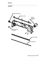
Page 95: ...Repair Information 4 27 4080 001 Carrier ...
Page 99: ...Repair Information 4 31 4080 001 Maintenance Station ...
Page 104: ...6 2 Service Manual 4080 001 ...
Page 106: ...7 2 Service Manual 4080 001 Assembly 1 Covers ...
Page 108: ...7 4 Service Manual 4080 001 Assembly 2 Frames ...
Page 110: ...7 6 Service Manual 4080 001 Assembly 3 Paper Feed ...
Page 112: ...7 8 Service Manual 4080 001 Assembly 4 Electronics ...
Page 114: ...7 10 Service Manual 4080 001 Assembly 5 Carrier ...
Page 116: ...7 12 Service Manual 4080 001 Assembly 6 Carrier Transport ...
Page 118: ...7 14 Service Manual 4080 001 Assembly 7 Maintenance Station ...


