4026-0XX
2-34
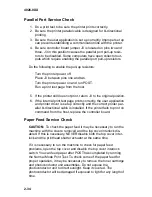
Parallel Port Service Check
1. Do a print test to be sure the printer prints correctly.
2. Be sure the printer parallel cable is designed for bi-directional
printing.
3. Be sure the user application is set up correctly. Improper set up
can prevent establishing a communication link with the printer.
4. Be sure controller board jumper J3 is located on pins two and
three. J3 in this position causes the parallel port pull-up resis-
tors to be disabled. Some computers have open collector out-
puts which require enabling the parallel port pull-up resistors.
Do the following to enable the pull-up resistors:
Turn the printer power off.
Place J3 between pins one and two.
Turn the printer power on and run POST.
Run a print test page from the host.
5. If the printer still does not print, return J3 to the original position.
6. If the internal print test page prints correctly, the user application
and printer driver is set up correctly and the correct printer par-
allel bi-directional cable is installed. If the printer fails to print on
command from the host, replace the controller board.
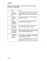
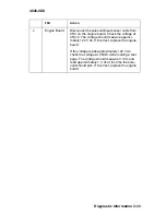
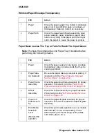
Paper Feed Service Check
CAUTION: To check the paper feed it may be necessary to run the
machine with the covers removed and the top cover interlock dis-
abled. If this is necessary, NEVER disable both the top cover inter-
lock and the printhead shutter actuator at the same time.
If it is necessary to run the machine to check for paper feed
problems, open the top cover and disable the top cover interlock
switch. You can feed paper after POST has completed by running
the Normal Mode Print Test. To check some of the paper feed for
proper operation, it may be necessary to remove the toner cartridge
and photoconductor unit assemblies. Do not expose the
photoconductor unit to direct sunlight. Keep it covered. The
photoconductor will be damaged if exposed to light for any length of
time.
Summary of Contents for Optra E
Page 8: ...viii Service Manual 4026 0XX ...
Page 15: ...Notices and Safety Information xv 4026 0XX Japanese Laser Notice Chinese Laser Notice ...
Page 72: ...4026 0XX 3 5 ...
Page 74: ...4026 0XX 3 7 ...
Page 101: ...4026 0XX Connector Locations 5 6 ...
Page 105: ...4026 0XX Connector Locations 5 10 ...
Page 108: ...4026 0XX 6 2 Assembly 1 Covers ...
Page 110: ...4026 0XX 6 4 Assembly 1 Covers continued ...
Page 112: ...4026 0XX 6 6 Assembly 2 Frame ...
Page 114: ...4026 0XX 6 8 Assembly 2 Frame continued ...
Page 116: ...4026 0XX 6 10 Assembly 2 Frame continued ...
Page 118: ...4026 0XX 6 12 Assembly 3 Printhead ...
Page 120: ...4026 0XX 6 14 Assembly 4 Paper Feed Input Tray ...
Page 122: ...4026 0XX 6 16 Assembly 5 Paper Feed Frame ...
Page 124: ...4026 0XX 6 18 Assembly 6 Fuser ...
Page 126: ...4026 0XX 6 20 Assembly 6 Fuser continued ...
Page 128: ...4026 0XX 6 22 Assembly 7 Electronics ...
Page 130: ...4026 0XX 6 24 Assembly 7 Electronics continued ...
Page 132: ...4026 0XX 6 26 Assembly 8 Transfer Assembly ...
Page 134: ...4026 0XX 6 28 Assembly 9 Option Second Paper Drawer ...
Page 136: ...4026 0XX 6 30 Assembly 9 Option Second Paper Drawer continued ...
Page 138: ...4026 0XX 6 32 Assembly 9 Option Second Paper Drawer continued ...

