Diagnostic Aids
3-27
4045-XXX
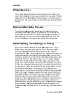
Printer Operation
The printer makes an image by applying toner dots to paper and
fusing them in place. The process is divided into two steps. The first
step is the Electrophotographic Process which forms the image on
the PC drum. The second step consists of Feeding, Transferring and
Fusing.
Electrophotographic Process
The photoconductive drum, located within the toner cartridge
assembly, creates the image to be printed on a page. As the PC
drum makes a full rotation, it is electrically charged, an image is
exposed to the PC drum, the image is developed with toner, the
toner is transferred to the paper, and the PC drum is cleaned.
Paper Feeding, Transferring and Fusing
Paper feeds into the printer from three different sources: Tray 1,
Multipurpose Feeder, and the optional Tray 2. When the printer
receives a printing command, the main drive motor turns on.
Depending upon the selected paper source, a pick roller solenoid is
actuated to allow the appropriate pick roller to turn. Paper is then
corner-fed via a D-roll type pick roller and travels along a paper path
toward the PC drum and transfer roller. An input sensor located
before the PC drum detects the leading edge of the paper. If the
paper is not detected within a certain time from when it was picked,
a paper jam is detected. After the paper passes through the sensor,
the paper travels between the PC drum and transfer roller. Toner is
drawn from the PC drum onto the paper via the electric field
produced from the transfer roller. While the toner is electrostatically
held to the paper, the paper travels to the fuser where the toner is
permanently fused to the paper. The fuser contains a hot roll and
backup roller which apply heat and pressure to the toner on the
paper as it passes through the fuser. As the paper exists the fuser, a
paper exit sensor detects the paper. If the exit sensor does not
detect the paper within a certain time from the input sensor, a paper
jam is detected. After the paper passes through the sensor, it is
directed either to the main exit bin or the rear exit (if the rear door is
open).
Summary of Contents for Optra M410
Page 6: ...vi Service Manual 4045 XXX ...
Page 8: ...viii Service Manual 4045 XXX Class 1 Laser Statement Label ...
Page 14: ...xiv Service Manual 4045 XXX Japanese Laser Notice Chinese Laser Notice ...
Page 20: ...xx Service Manual 4045 XXX ...
Page 26: ...1 6 Service Manual 4045 XXX ...
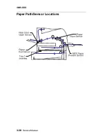
Page 102: ...3 28 Service Manual 4045 XXX Paper Path Sensor Locations ...
Page 103: ...Diagnostic Aids 3 29 4045 XXX Cable Locations ...
Page 104: ...3 30 Service Manual 4045 XXX ...
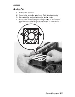
Page 116: ...4 12 Service Manual 4045 XXX 5 Remove the cooling fan ...
Page 137: ...Connector Locations 5 3 4045 XXX ...
Page 143: ...Connector Locations 5 9 4045 XXX ...
Page 145: ...Connector Locations 5 11 4045 XXX ...
Page 147: ...Connector Locations 5 13 4045 XXX ...
Page 148: ...5 14 Service Manual 4045 XXX ...
Page 150: ...6 2 Service Manual 4045 XXX Assembly 1 Covers ...
Page 152: ...6 4 Service Manual 4045 XXX Assembly 1 Covers continued ...
Page 154: ...6 6 Service Manual 4045 XXX Assembly 2 Frame ...
Page 156: ...6 8 Service Manual 4045 XXX Assembly 3 Printhead ...
Page 158: ...6 10 Service Manual 4045 XXX Assembly 4 Paper Feed Multipurpose Unit ...
Page 160: ...6 12 Service Manual 4045 XXX Assembly 5 Paper Feed Alignment ...
Page 162: ...6 14 Service Manual 4045 XXX Assembly 6 Paper Feed Output ...
Page 164: ...6 16 Service Manual 4045 XXX Assembly 7 Main Drive ...
Page 166: ...6 18 Service Manual 4045 XXX Assembly 8 Developer Drive ...
Page 168: ...6 20 Service Manual 4045 XXX Assembly 9 Fuser ...
Page 170: ...6 22 Service Manual 4045 XXX Assembly 9 Fuser continued ...
Page 172: ...6 24 Service Manual 4045 XXX Assembly 10 Transfer ...
Page 174: ...6 26 Service Manual 4045 XXX Assembly 11 Charging ...
Page 176: ...6 28 Service Manual 4045 XXX Assembly 12 Electronics ...
Page 178: ...6 30 Service Manual 4045 XXX Assembly 12 Electronics continued ...
Page 180: ...6 32 Service Manual 4045 XXX Assembly 12 Electronics continued ...
Page 182: ...6 34 Service Manual 4045 XXX Assembly 13 250 Sheet Tray ...
Page 184: ...6 36 Service Manual 4045 XXX Assembly 14 500 Sheet Tray ...
Page 186: ...6 38 Service Manual 4045 XXX Assembly 14 500 Sheet Tray continued ...


