4-2
Service Manual
4045-XXX
Adjustment Procedures
Printhead Assembly
This adjustment must be performed whenever the printhead is
removed, replaced or the printhead mounting screws are loosened.
An incorrectly adjusted printhead produces horizontally skewed
images down the page.
To perform the printhead adjustment:
1. Turn the printer off.
2. Press and hold Return and Go.
3. Turn the printer On and release the buttons when “Performing
Self Test” displays.
4. Select Print Test, Tray 1 and Single from the menu. The test
page should only be printed on letter or A4 paper from Tray 1.
The Print Test page consists of horizontal lines that can be used
for skew adjustment, page count setting, printer serial number
code levels and print registration settings.
5. Check the Print Test page for any sign of skew by folding the
paper in half (left edge to right edge). Check the horizontal lines
at the top left and top right of the test page for equal distance
from the top of the page. If any adjustment is necessary,
perform the following:
a. Remove the top cover.
b. Loosen the three printhead mounting screws.
c. Adjust the position of the printhead.
d. Replace the top cover.
e. Print a Print Test page and check for skew again.
This procedure may take two or three attempts before you get
satisfactory results.
6. When you have the correct printhead adjustment, gently tighten
the three printhead mounting screws being careful not to move
the printhead assembly.
Summary of Contents for Optra M410
Page 6: ...vi Service Manual 4045 XXX ...
Page 8: ...viii Service Manual 4045 XXX Class 1 Laser Statement Label ...
Page 14: ...xiv Service Manual 4045 XXX Japanese Laser Notice Chinese Laser Notice ...
Page 20: ...xx Service Manual 4045 XXX ...
Page 26: ...1 6 Service Manual 4045 XXX ...
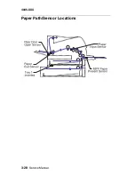
Page 102: ...3 28 Service Manual 4045 XXX Paper Path Sensor Locations ...
Page 103: ...Diagnostic Aids 3 29 4045 XXX Cable Locations ...
Page 104: ...3 30 Service Manual 4045 XXX ...
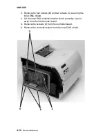
Page 116: ...4 12 Service Manual 4045 XXX 5 Remove the cooling fan ...
Page 137: ...Connector Locations 5 3 4045 XXX ...
Page 143: ...Connector Locations 5 9 4045 XXX ...
Page 145: ...Connector Locations 5 11 4045 XXX ...
Page 147: ...Connector Locations 5 13 4045 XXX ...
Page 148: ...5 14 Service Manual 4045 XXX ...
Page 150: ...6 2 Service Manual 4045 XXX Assembly 1 Covers ...
Page 152: ...6 4 Service Manual 4045 XXX Assembly 1 Covers continued ...
Page 154: ...6 6 Service Manual 4045 XXX Assembly 2 Frame ...
Page 156: ...6 8 Service Manual 4045 XXX Assembly 3 Printhead ...
Page 158: ...6 10 Service Manual 4045 XXX Assembly 4 Paper Feed Multipurpose Unit ...
Page 160: ...6 12 Service Manual 4045 XXX Assembly 5 Paper Feed Alignment ...
Page 162: ...6 14 Service Manual 4045 XXX Assembly 6 Paper Feed Output ...
Page 164: ...6 16 Service Manual 4045 XXX Assembly 7 Main Drive ...
Page 166: ...6 18 Service Manual 4045 XXX Assembly 8 Developer Drive ...
Page 168: ...6 20 Service Manual 4045 XXX Assembly 9 Fuser ...
Page 170: ...6 22 Service Manual 4045 XXX Assembly 9 Fuser continued ...
Page 172: ...6 24 Service Manual 4045 XXX Assembly 10 Transfer ...
Page 174: ...6 26 Service Manual 4045 XXX Assembly 11 Charging ...
Page 176: ...6 28 Service Manual 4045 XXX Assembly 12 Electronics ...
Page 178: ...6 30 Service Manual 4045 XXX Assembly 12 Electronics continued ...
Page 180: ...6 32 Service Manual 4045 XXX Assembly 12 Electronics continued ...
Page 182: ...6 34 Service Manual 4045 XXX Assembly 13 250 Sheet Tray ...
Page 184: ...6 36 Service Manual 4045 XXX Assembly 14 500 Sheet Tray ...
Page 186: ...6 38 Service Manual 4045 XXX Assembly 14 500 Sheet Tray continued ...


