Diagnostic Aids
3-25
4045-XXX
Cooling Fan / Fuser Control Test
This test lets you turn on the cooling fan to slow and fast speeds.
The fuser warms to standby temperature when the fan is set to slow
speed and to printing temperature when the fan is set to fast speed.
The fuser turns off when the fan turns off.
To run the Cooling Fan Test/Fuser Control Test:
1. Select Cooling Fan (status) from the menu. Status displays the
current status of the fan (Stop, Slow, or Fast).
2. Press GO to turn the fan on to Fast. Pressing GO again
alternates the fan speed from Fast to Slow. Press STOP to turn
the fan off.
Once the cooling fan turns on, press the right menu > button to
monitor fuser temperature rise. "Heating Print" displays on the top
line of the operator panel. The number displayed on the bottom left
of the operator panel is a preset thermistor value corresponding to
either standby or printing fuser temperatures, depending on whether
the cooling fan is set to slow or fast. The number displayed on the
bottom right of the operator panel is the current thermistor value.
This value increases from 0 and stabilizes somewhat near the preset
thermistor value. The numbers themselves are not actual
temperature measurements. However, the higher the value, the
higher the thermistor temperature. The two numbers are used only
in comparison with each other to assure the fuser temperature
control system is working properly.
Note:
The message “Error!! 00 10 24” displays if the thermistor is
disconnected or defective. The message “Error!! 00 20 23” displays
if the thermistor detects the fuser is too hot or if the thermistor circuit
is shorted.
Summary of Contents for Optra M410
Page 6: ...vi Service Manual 4045 XXX ...
Page 8: ...viii Service Manual 4045 XXX Class 1 Laser Statement Label ...
Page 14: ...xiv Service Manual 4045 XXX Japanese Laser Notice Chinese Laser Notice ...
Page 20: ...xx Service Manual 4045 XXX ...
Page 26: ...1 6 Service Manual 4045 XXX ...
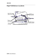
Page 102: ...3 28 Service Manual 4045 XXX Paper Path Sensor Locations ...
Page 103: ...Diagnostic Aids 3 29 4045 XXX Cable Locations ...
Page 104: ...3 30 Service Manual 4045 XXX ...
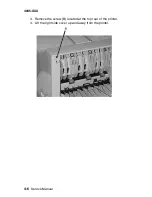
Page 116: ...4 12 Service Manual 4045 XXX 5 Remove the cooling fan ...
Page 137: ...Connector Locations 5 3 4045 XXX ...
Page 143: ...Connector Locations 5 9 4045 XXX ...
Page 145: ...Connector Locations 5 11 4045 XXX ...
Page 147: ...Connector Locations 5 13 4045 XXX ...
Page 148: ...5 14 Service Manual 4045 XXX ...
Page 150: ...6 2 Service Manual 4045 XXX Assembly 1 Covers ...
Page 152: ...6 4 Service Manual 4045 XXX Assembly 1 Covers continued ...
Page 154: ...6 6 Service Manual 4045 XXX Assembly 2 Frame ...
Page 156: ...6 8 Service Manual 4045 XXX Assembly 3 Printhead ...
Page 158: ...6 10 Service Manual 4045 XXX Assembly 4 Paper Feed Multipurpose Unit ...
Page 160: ...6 12 Service Manual 4045 XXX Assembly 5 Paper Feed Alignment ...
Page 162: ...6 14 Service Manual 4045 XXX Assembly 6 Paper Feed Output ...
Page 164: ...6 16 Service Manual 4045 XXX Assembly 7 Main Drive ...
Page 166: ...6 18 Service Manual 4045 XXX Assembly 8 Developer Drive ...
Page 168: ...6 20 Service Manual 4045 XXX Assembly 9 Fuser ...
Page 170: ...6 22 Service Manual 4045 XXX Assembly 9 Fuser continued ...
Page 172: ...6 24 Service Manual 4045 XXX Assembly 10 Transfer ...
Page 174: ...6 26 Service Manual 4045 XXX Assembly 11 Charging ...
Page 176: ...6 28 Service Manual 4045 XXX Assembly 12 Electronics ...
Page 178: ...6 30 Service Manual 4045 XXX Assembly 12 Electronics continued ...
Page 180: ...6 32 Service Manual 4045 XXX Assembly 12 Electronics continued ...
Page 182: ...6 34 Service Manual 4045 XXX Assembly 13 250 Sheet Tray ...
Page 184: ...6 36 Service Manual 4045 XXX Assembly 14 500 Sheet Tray ...
Page 186: ...6 38 Service Manual 4045 XXX Assembly 14 500 Sheet Tray continued ...


