


Repair Information
4-19
Infoprint 1120 and 1125
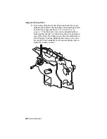
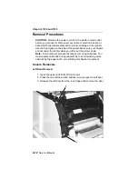
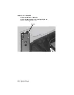
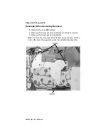
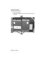
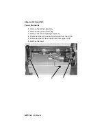
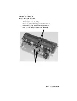
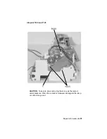
Duplex Board Removal
1. Lift the base printer from the duplex assembly.
2. Remove the four duplex board cover mounting screws.
3. Gently disconnect the cables from the duplex board.
Warning: To avoid damage to the cables and connectors.
4. Remove the two duplex board mounting screws and remove the
duplex board.
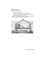
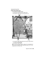
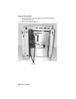
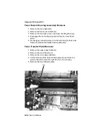
Duplex Front Cover Assembly Removal
1. Lift the base printer from the duplex assembly.
2. Remove the four duplex board cover mounting screws and
disconnect the duplex cover door switch cable at connector J6.
3. Position the duplex assembly on its side.
4. Gently release the three front cover assembly latches from the
bottom of the duplex assembly.
5. Remove the duplex front cover assembly.
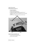
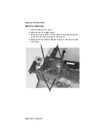
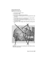
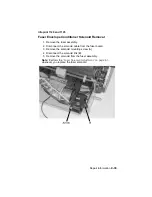
Duplex Front Cover Door Removal
1. Remove the duplex front cover assembly.
2. Holding the front of the assembly away from you, open the
cover door and gently pry the left side door pivot from the
mounting.
3. Move the cover door to the left to clear the right door pivot from
the mounting and remove the duplex front cover door.
Summary of Contents for Optra T522
Page 7: ...viii Service Manual Infoprint 1120 and 1125 ...
Page 9: ...x Service Manual Infoprint 1120 and 1125 Class 1 Laser Statement Label ...
Page 23: ...xxiv Service Manual Infoprint 1120 and 1125 ...
Page 161: ...3 30 Service Manual Infoprint 1120 and 1125 ...
Page 223: ...5 2 Service Manual Infoprint 1120 and 1125 ...
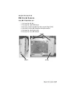
Page 230: ...Connector Locations 5 9 Infoprint 1120 and 1125 Engine Board ...
Page 231: ...5 10 Service Manual Infoprint 1120 and 1125 Controller Board Non Network ...
Page 232: ...Connector Locations 5 11 Infoprint 1120 and 1125 Controller Board Network ...
Page 234: ...Connector Locations 5 13 Infoprint 1120 and 1125 ...
Page 236: ...Connector Locations 5 15 Infoprint 1120 and 1125 210 220 001 002 ...
Page 238: ...Connector Locations 5 17 Infoprint 1120 and 1125 ...
Page 241: ...5 20 Service Manual Infoprint 1120 and 1125 ...
Page 245: ...7 2 Service Manual Infoprint 1120 and 1125 Assembly 1 Covers ...
Page 247: ...7 4 Service Manual Infoprint 1120 and 1125 Assembly 2 Frame ...
Page 249: ...7 6 Service Manual Infoprint 1120 and 1125 Assembly 2 Frame continued ...
Page 251: ...7 8 Service Manual Infoprint 1120 and 1125 Assembly 3 Printhead ...
Page 253: ...7 10 Service Manual Infoprint 1120 and 1125 Assembly 4 Paper Feed Autocompensator ...
Page 255: ...7 12 Service Manual Infoprint 1120 and 1125 Assembly 5 Paper Feed Multipurpose Unit ...
Page 257: ...7 14 Service Manual Infoprint 1120 and 1125 Assembly 6 Paper Feed Alignment ...
Page 259: ...7 16 Service Manual Infoprint 1120 and 1125 Assembly 7 Paper Feed Output ...
Page 261: ...7 18 Service Manual Infoprint 1120 and 1125 Assembly 8 Integrated Paper Tray 500 Sheet ...
Page 263: ...7 20 Service Manual Infoprint 1120 and 1125 Assembly 9 Main Drive ...
Page 265: ...7 22 Service Manual Infoprint 1120 and 1125 Assembly 10 Developer Drive ...
Page 267: ...7 24 Service Manual Infoprint 1120 and 1125 Assembly 11 Hot Roll Fuser ...
Page 269: ...7 26 Service Manual Infoprint 1120 and 1125 Assembly 12 Transfer ...
Page 271: ...7 28 Service Manual Infoprint 1120 and 1125 Assembly 13 Charging ...
Page 273: ...7 30 Service Manual Infoprint 1120 and 1125 Assembly 14 Electronics 1 ...
Page 275: ...7 32 Service Manual Infoprint 1120 and 1125 Assembly 14 Electronics I continued ...
Page 277: ...7 34 Service Manual Infoprint 1120 and 1125 Assembly 15 Electronics II ...
Page 279: ...7 36 Service Manual Infoprint 1120 and 1125 Assembly 16 Electronics III ...
Page 281: ...7 38 Service Manual Infoprint 1120 and 1125 Assembly 17 Electronics IV ...
Page 283: ...7 40 Service Manual Infoprint 1120 and 1125 Assembly 18 Electronics V ...
Page 285: ...7 42 Service Manual Infoprint 1120 and 1125 Assembly 19 Electronics VI ...
Page 287: ...7 44 Service Manual Infoprint 1120 and 1125 Assembly 20 250 Sheet Tray ...
Page 289: ...7 46 Service Manual Infoprint 1120 and 1125 Assembly 20 250 Sheet Tray continued ...
Page 291: ...7 48 Service Manual Infoprint 1120 and 1125 Assembly 21 Integrated Paper Tray 250 Sheet ...
Page 293: ...7 50 Service Manual Infoprint 1120 and 1125 Assembly 22 500 Sheet Tray ...
Page 295: ...7 52 Service Manual Infoprint 1120 and 1125 Assembly 22 500 Sheet Tray continued ...
Page 297: ...7 54 Service Manual Infoprint 1120 and 1125 Assembly 23 Duplex Unit ...
Page 299: ...7 56 Service Manual Infoprint 1120 and 1125 Assembly 23 Duplex Unit continued ...
Page 301: ...7 58 Service Manual Infoprint 1120 and 1125 Assembly 23 Duplex Unit continued ...
Page 303: ...7 60 Service Manual Infoprint 1120 and 1125 Assembly 24 Envelope Feeder ...
Page 305: ...7 62 Service Manual Infoprint 1120 and 1125 Assembly 25 High Capacity Feeder ...
Page 307: ...7 64 Service Manual Infoprint 1120 and 1125 Assembly 25 High Capacity Feeder continued ...
Page 309: ...7 66 Service Manual Infoprint 1120 and 1125 Assembly 25 High Capacity Feeder continued ...
Page 311: ...7 68 Service Manual Infoprint 1120 and 1125 Assembly 25 High Capacity Feeder continued ...
Page 313: ...7 70 Service Manual Infoprint 1120 and 1125 Assembly 25 High Capacity Feeder continued ...
Page 315: ...7 72 Service Manual Infoprint 1120 and 1125 Assembly 26 Kiosk Vertical Paper Adapter ...
Page 317: ...7 74 Service Manual Infoprint 1120 and 1125 Assembly 27 Kiosk Horizontal Paper Adapter ...
Page 323: ...7 80 Service Manual Infoprint 1120 and 1125 ...
Page 333: ...I 10 Service Manual Infoprint 1120 and 1125 ...


