Locations and connections
5-3
4048-1xx
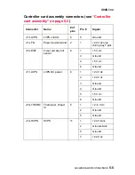
Controller card assembly connectors (see
“Controller
card assembly” on page 5-2
)
Connector
Name
# of
pins
Pin #
Signal
J1–MMTR
Mirror motor
5
4
Ground
5
+24 V dc
J2–CO
Cover 3
2
+5 V dc
3
Ground
J3–LSU
LSU (printhead)
10
3
Ground
6
Ground
7
+5 V dc (cover
closed)
9
Ground
J4–DIMM
SDRAM
100
1
Ground
12
Ground
21
+3.3 V dc
26
Ground
36
Ground
42
+3.3 V dc
47
Ground
50
+3.3 V dc
51
Ground
56
+3.3 V dc
62
Ground
71
+3.3 V dc
76
Ground
81
+3.3 V dc
Summary of Contents for T 430
Page 14: ...xiv Service Manual 4048 1xx Japanese Laser Notice Chinese Laser Notice ...
Page 15: ...Laser notices xv 4048 1xx Korean Laser Notice ...
Page 16: ...xvi Service Manual 4048 1xx ...
Page 21: ...Safety information xxi 4048 1xx ...
Page 34: ...1 12 Service Manual 4048 1xx ...
Page 122: ...3 28 Service Manual 4048 1xx ...
Page 143: ...Repair information 4 21 4048 1xx 8 Disconnect the cable from the operator panel card ...
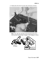
Page 202: ...4 80 Service Manual 4048 1xx 8 Remove the bellcrank while holding the link guide ...
Page 205: ...Locations and connections 5 1 4048 1xx 5 Locations and connections Exterior locations ...
Page 216: ...6 4 Service Manual 4048 1xx ...
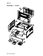
Page 218: ...7 2 Service Manual 4048 1xx Assembly 1 Covers ...
Page 220: ...7 4 Service Manual 4048 1xx Assembly 2 Paper feed ...
Page 222: ...7 6 Service Manual 4048 1xx Assembly 3 Frame ...
Page 226: ...7 10 Service Manual 4048 1xx Assembly 6 Charging ...
Page 228: ...7 12 Service Manual 4048 1xx Assembly 7 Electronics and cables 1 ...
Page 230: ...7 14 Service Manual 4048 1xx Assembly 8 Electronics and cables 2 ...
Page 232: ...7 16 Service Manual 4048 1xx Assembly 8 cont Electronics and cables II ...
Page 234: ...7 18 Service Manual 4048 1xx Assembly 9 Sensors ...
Page 236: ...7 20 Service Manual 4048 1xx Assembly 10 Options 1 2 3 4 ...
Page 249: ......


