Diagnostic information
2-67
4060-
xxx
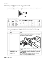
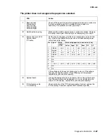
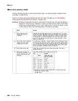
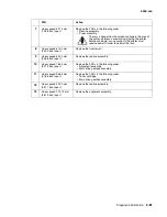
The printer does not recognize the paper size selected.
FRU
Action
1
Back restraint
Side restraint
Snap-in plate
Autosize slider
Autosize finger
Check all the paper size parts for damage or broken parts. make sure
the parts operate correctly. If a problem is found, repair as
necessary. If no problem is found, go to step 2.
2
Switch activate spring
Make sure the switch activate spring is not bent or broken. Replace
the spring if damaged. If the spring is not damaged, go to step 3.
3
Internal tray card (ITC)
System board
ITC cable
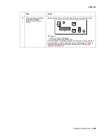
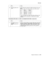
Set the tray for the paper size that is not recognized and install the
tray in the printer. Select the paper size and corresponding paper
switch from table, below.
If the voltage on J34 does not change, go to step 4. If the voltage
changes, recheck the printer. If Tray 1Missing is still displayed,
replace the system board assembly.
4
System board
Ground the appropriate pin on connector J34 on the system board.
Tray 1 Missing should not be displayed. If it is not displayed, go to
step 5. If it still displays, replace the system board assembly.
5
ITC/autocomp cable
ITC assembly
Check continuity of the ITC/Autocomp cable. If correct, replace the
ITC assembly. If incorrect, replace the ITC/autocomp cable.
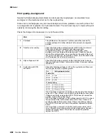
Pin
Signal
Static
tray out
(V dc)
Static with paper tray in and set to: (V dc)
Letter
Legal
A4
Exec
B5
A5
1
PSIZE2
+3.3 0
0
+3.3
+3.3
0
+3.3
2
Ground
0
0
0
0
0
0
0
3
PSIZE1
+3.3
+3.3
+3.3
0
0
0
+3.3
4
PSIZE3
+3.3
0
+3.3
+3.3
0
+3.3
0
5
N/A
6
N/A
7
N/A
8
+3.3
+3.3
+3.3
+3.3
+3.3
+3.3
+3.3
+3.3
9
N/A
10
N/A
Summary of Contents for T63 Series
Page 13: ...Laser notices xiii 4060 xxx Japanese Laser Notice ...
Page 14: ...xiv Service Manual 4060 xxx Korean Laser Notice ...
Page 34: ...1 16 Service Manual 4060 xxx ...
Page 218: ...4 64 Service Manual 4060 xxx ...
Page 236: ...6 2 Service Manual 4060 xxx ...
Page 238: ...7 2 Service Manual 4060 xxx Assembly 1 Covers ...
Page 240: ...7 4 Service Manual 4060 xxx Assembly 2 Frame 1 5 2 1 3 4 3 4 8 6 7 ...
Page 252: ...7 16 Service Manual 4060 xxx Assembly 9 Paper feed alignment 3 2 1 4 ...
Page 258: ...7 22 Service Manual 4060 xxx Assembly 12 Drives Main drive and developer drive 3 2 4 1 7 6 5 ...
Page 260: ...7 24 Service Manual 4060 xxx Assembly 13 Hot roll fuser 3 7 5 2 6 4 1 5 8 7 9 ...
Page 262: ...7 26 Service Manual 4060 xxx Assembly 14 Transfer charging 3 2 4 1 5 6 7 9 10 8 ...
Page 264: ...7 28 Service Manual 4060 xxx Assembly 15 Electronics power supplies 3 7 5 2 6 4 1 ...
Page 266: ...7 30 Service Manual 4060 xxx Assembly 16 Electronics card assemblies 3 1 4 5 6 9 2 4 7 8 10 ...
Page 268: ...7 32 Service Manual 4060 xxx Assembly 17 Electronics shields ...
Page 270: ...7 34 Service Manual 4060 xxx Assembly 18 Cabling diagrams 1 3 1 2 4 5 6 7 8 7 4 ...
Page 272: ...7 36 Service Manual 4060 xxx Assembly 19 Cabling diagrams 2 HVPS LVPS 3 5 4 1 2 6 ...
Page 276: ...7 40 Service Manual 4060 xxx Assembly 21 250 sheet paper tray ...
Page 284: ...7 48 Service Manual 4060 xxx Assembly 23 Duplex option 1 ...
Page 286: ...7 50 Service Manual 4060 xxx Assembly 24 Envelope feeder 3 11 7 13 5 9 2 10 6 4 12 8 14 1 ...
Page 288: ...7 52 Service Manual 4060 xxx Assembly 25 Output expander ...
Page 290: ...7 54 Service Manual 4060 xxx Assembly 25 cont Output expander ...
Page 292: ...7 56 Service Manual 4060 xxx Assembly 26 High capacity output expander ...
Page 296: ...7 60 Service Manual 4060 xxx Assembly 27 5 bin mailbox ...
Page 298: ...7 62 Service Manual 4060 xxx Assembly 27 cont 5 bin mailbox ...
Page 300: ...7 64 Service Manual 4060 xxx Assembly 28 High capacity feeder 1 ...
Page 320: ...7 84 Service Manual 4060 xxx Assembly 38 StapleSmart finisher 4 1 ...
Page 344: ...I 20 Service Manual 4060 xxx ...
Page 345: ......

