Diagnostic information
2-81
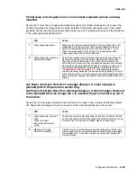
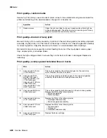
4060-
xxx
7
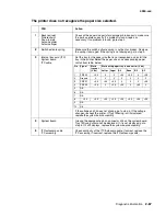
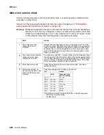
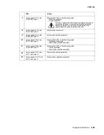
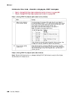
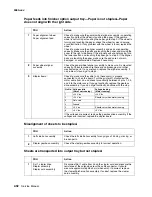
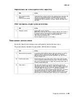
Lines spaced 49.74 mm
(1.958 inch) apart
Replace the FRUs in the following order:
• Redrive assembly
• Fuser assembly
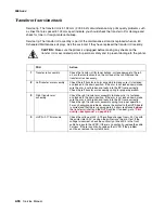
There is a danger from hazardous voltage in the area of
the printer where you are working. Unplug the printer
before you begin, or use caution if the printer must
receive power in order to perform the task.
8
Lines spaced 51.02 mm
(2.009 inch) apart
Replace the transfer roll.
9
Lines spaced 52.23 mm
(2.056 inch) apart
Replace the redrive assembly.
10
Lines spaced 76.53 mm
(3.013 inch) apart
Replace the FRUs in the following order:
• Alignment assembly
• Main drive gearbox assembly
11
Lines spaced 95.66 mm
(3.766 inch) apart
Replace the FRUs in the following order:
• Toner cartridge
• Main drive gearbox assembly
12
Lines spaced 99.49 mm
(3.917 inch) apart
Replace the redrive assembly.
13
Lines spaced 114.79 mm
(4.519 inch) apart
Replace the alignment assembly.
FRU
Action
Summary of Contents for T63 Series
Page 13: ...Laser notices xiii 4060 xxx Japanese Laser Notice ...
Page 14: ...xiv Service Manual 4060 xxx Korean Laser Notice ...
Page 34: ...1 16 Service Manual 4060 xxx ...
Page 218: ...4 64 Service Manual 4060 xxx ...
Page 236: ...6 2 Service Manual 4060 xxx ...
Page 238: ...7 2 Service Manual 4060 xxx Assembly 1 Covers ...
Page 240: ...7 4 Service Manual 4060 xxx Assembly 2 Frame 1 5 2 1 3 4 3 4 8 6 7 ...
Page 252: ...7 16 Service Manual 4060 xxx Assembly 9 Paper feed alignment 3 2 1 4 ...
Page 258: ...7 22 Service Manual 4060 xxx Assembly 12 Drives Main drive and developer drive 3 2 4 1 7 6 5 ...
Page 260: ...7 24 Service Manual 4060 xxx Assembly 13 Hot roll fuser 3 7 5 2 6 4 1 5 8 7 9 ...
Page 262: ...7 26 Service Manual 4060 xxx Assembly 14 Transfer charging 3 2 4 1 5 6 7 9 10 8 ...
Page 264: ...7 28 Service Manual 4060 xxx Assembly 15 Electronics power supplies 3 7 5 2 6 4 1 ...
Page 266: ...7 30 Service Manual 4060 xxx Assembly 16 Electronics card assemblies 3 1 4 5 6 9 2 4 7 8 10 ...
Page 268: ...7 32 Service Manual 4060 xxx Assembly 17 Electronics shields ...
Page 270: ...7 34 Service Manual 4060 xxx Assembly 18 Cabling diagrams 1 3 1 2 4 5 6 7 8 7 4 ...
Page 272: ...7 36 Service Manual 4060 xxx Assembly 19 Cabling diagrams 2 HVPS LVPS 3 5 4 1 2 6 ...
Page 276: ...7 40 Service Manual 4060 xxx Assembly 21 250 sheet paper tray ...
Page 284: ...7 48 Service Manual 4060 xxx Assembly 23 Duplex option 1 ...
Page 286: ...7 50 Service Manual 4060 xxx Assembly 24 Envelope feeder 3 11 7 13 5 9 2 10 6 4 12 8 14 1 ...
Page 288: ...7 52 Service Manual 4060 xxx Assembly 25 Output expander ...
Page 290: ...7 54 Service Manual 4060 xxx Assembly 25 cont Output expander ...
Page 292: ...7 56 Service Manual 4060 xxx Assembly 26 High capacity output expander ...
Page 296: ...7 60 Service Manual 4060 xxx Assembly 27 5 bin mailbox ...
Page 298: ...7 62 Service Manual 4060 xxx Assembly 27 cont 5 bin mailbox ...
Page 300: ...7 64 Service Manual 4060 xxx Assembly 28 High capacity feeder 1 ...
Page 320: ...7 84 Service Manual 4060 xxx Assembly 38 StapleSmart finisher 4 1 ...
Page 344: ...I 20 Service Manual 4060 xxx ...
Page 345: ......

