


2-8
Service Manual
7510
Go Back
Previous
Next
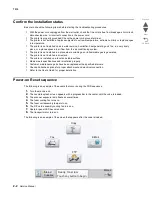
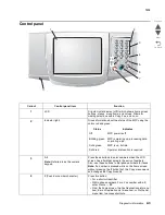
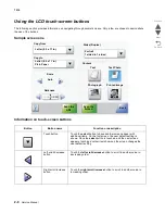
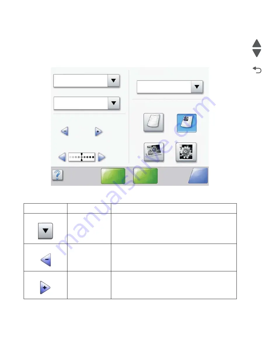
Using the LCD touch-screen buttons
The following section provides information on navigating through several screens. Only a few are chosen to demonstrate
the use of the buttons.
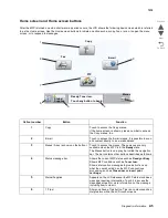
Sample screen one
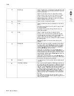
Information on touch-screen buttons
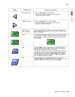
Button
Button name
Function or description
Touch button
Touch the
select
button to have another screen appear with
additional items. On the first screen, the user default setting is
shown. Once the
select
button is touched, and the next screen
appears, touching another item shown on the screen changes the
user default setting.
Left scroll decrease
button
Touch the
left scroll decrease
button to scroll to another value in
decreasing order.
Right scroll increase
button
Touch the
right scroll increase
button to scroll to another value in
increasing order.
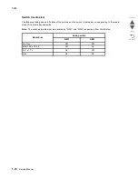
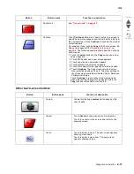
Copy from
Letter (8.5 x 11 in.)
Copy to
Letter (8.5 x 11 in.)
Plain Paper
Sides (Duplex)
Portrait
1-sided to 1-sided
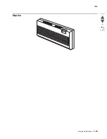
Content
Scale
Auto
Darkness
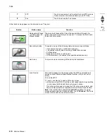
Scan the
ADF
Scan the
flatbed
Back
Text
Text/Photo
Photograph
Printed Image
Summary of Contents for X945E
Page 20: ...xx Service Manual 7510 Go Back Previous Next ...
Page 25: ...Notices and safety information xxv 7510 Go Back Previous Next ...
Page 26: ...xxvi Service Manual 7510 Go Back Previous Next ...
Page 32: ...xxxii Service Manual 7510 Go Back Previous Next ...
Page 88: ...1 56 Service Manual 7510 Go Back Previous Next TTM theory ...
Page 97: ...General information 1 65 7510 Go Back Previous Next 3TM theory ...
Page 104: ...1 72 Service Manual 7510 Go Back Previous Next 1TM theory ...
Page 111: ...General information 1 79 7510 Go Back Previous Next Duplex ...
Page 432: ...3 52 Service Manual 7510 Go Back Previous Next ...
Page 475: ...Repair information 4 43 7510 Go Back Previous Next E F ...
Page 483: ...Repair information 4 51 7510 Go Back Previous Next Connectors A ...
Page 623: ...Repair information 4 191 7510 Go Back Previous Next ...
Page 653: ...Repair information 4 221 7510 Go Back Previous Next ...
Page 714: ...4 282 Service Manual 7510 Go Back Previous Next ...
Page 715: ...Connector locations 5 1 7510 Go Back Previous Next 5 Connector locations Locations ...
Page 720: ...5 6 Service Manual 7510 Go Back Previous Next Printhead Polygon mirror motor ...
Page 725: ...Connector locations 5 11 7510 Go Back Previous Next ...
Page 726: ...5 12 Service Manual 7510 Go Back Previous Next ...
Page 729: ...Connector locations 5 15 7510 Go Back Previous Next Switch media size Switch TTM media size ...
Page 765: ...Parts catalog 7 31 7510 Go Back Previous Next Assembly 29 Electrical 1 3 5 9 2 10 6 4 8 1 7 ...
Page 770: ...7 36 MFP Service Manual 7510 Go Back Previous Next Assembly 32 Electrical 4 2 1 4 3 5 7 6 8 9 ...
Page 797: ...Parts catalog 7 63 7510 Go Back Previous Next Assembly 50 1TM feed unit assembly 4 3 5 4 1 2 ...
Page 802: ...7 68 MFP Service Manual 7510 Go Back Previous Next Assembly 53 1TM drive and electrical ...
Page 804: ...7 70 MFP Service Manual 7510 Go Back Previous Next Assembly 54 3TM covers 3 5 2 4 1 ...
Page 812: ...7 78 MFP Service Manual 7510 Go Back Previous Next Assembly 58 3TM drive and electrical ...
Page 815: ...Parts catalog 7 81 7510 Go Back Previous Next Assembly 60 TTM media trays 3 5 4 3 7 2 6 8 1 ...
Page 824: ...7 90 MFP Service Manual 7510 Go Back Previous Next Assembly 67 TTM drive and electrical ...
Page 828: ...7 94 MFP Service Manual 7510 Go Back Previous Next ...
Page 836: ...I 8 Service Manual 7510 Go Back Previous Next ...
Page 844: ...I 16 Service Manual 7510 Go Back Previous Next ...