


Diagnostic information
2-29
7510
Go Back
Previous
Next
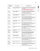
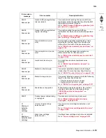
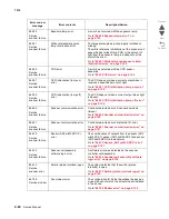
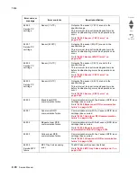
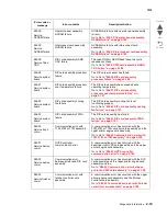
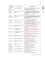
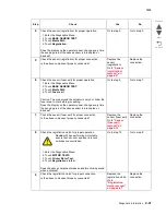
920.02
Service fuser
error
Fuser sub lamp overheat
error
The rear thermistor detected an abnormal high
temperature.
This error must be reset inside diagnostic mode
before troubleshooting or machine operation can
occur.
Go to
“920.02 Fuser sub lamp overheat error” on
page 2-175
.
920.03
Service fuser
error
Rear thermistor
disconnection error
The system detected an open circuit in the fuser
rear thermistor.
Go to
“920.03 Rear thermistor disconnection
error” on page 2-175
.
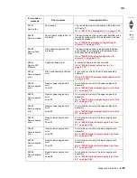
920.04
Service fuser
error
Main lamp warm up error
The fuser temperature did not reach the ready
temperature in the specified time or the incorrect
voltage fuser is installed.
Go to
“920.04 Main lamp warm up error” on
page 2-176
.
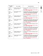
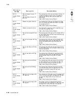
920.05
Service fuser
error
Main lamp on-time error
The main lamp was turned on for 20 seconds or
longer.
Go to
“920.05 Main lamp on-time error” on
page 2-177
.
920.06
Service fuser
error
Sub lamp warm up error
The fuser temperature did not reach the ready
temperature in the specified time.
Go to
“920.06 Sub lamp warm-up failure” on
page 2-177
.
920.07
Service fuser
error
Sub lamp on-time error
The Sub lamp was turned on for 20 seconds or
longer.
Go to
“920.07 Sub lamp on-time error” on
page 2-178
.
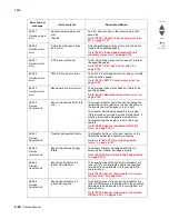
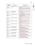
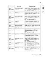
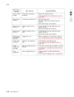
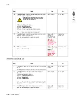
924.00
Service engine
error
Yellow PC smartchip
communication error
Communication error with the Y PC drum contact
chip problem has occurred.
Go to
“924.00 Yellow PC smartchip
communication error” on page 2-178
924.01
Service engine
error
Magenta PC smartchip
communication error
Communication error with the M PC drum contact
chip problem has occurred.
Go to
“924.01 Magenta PC smartchip
communication error” on page 2-179
.
924.02
Service engine
error
Cyan PC smartchip
communication error
Communication error with the C PC drum contact
chip problem has occurred.
Go to
“924.02 Cyan PC smartchip
communication error” on page 2-180
.
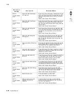
924.03
Service engine
error
Black PC smartchip
communication error
Communication error with the K PC drum contact
chip problem has occurred.
Go to
“924.03 Black PC smartchip
communication error” on page 2-180
.
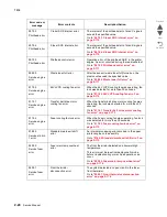
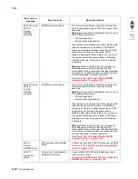
Error code or
message
Error contents
Description/Action
Summary of Contents for X945E
Page 20: ...xx Service Manual 7510 Go Back Previous Next ...
Page 25: ...Notices and safety information xxv 7510 Go Back Previous Next ...
Page 26: ...xxvi Service Manual 7510 Go Back Previous Next ...
Page 32: ...xxxii Service Manual 7510 Go Back Previous Next ...
Page 88: ...1 56 Service Manual 7510 Go Back Previous Next TTM theory ...
Page 97: ...General information 1 65 7510 Go Back Previous Next 3TM theory ...
Page 104: ...1 72 Service Manual 7510 Go Back Previous Next 1TM theory ...
Page 111: ...General information 1 79 7510 Go Back Previous Next Duplex ...
Page 432: ...3 52 Service Manual 7510 Go Back Previous Next ...
Page 475: ...Repair information 4 43 7510 Go Back Previous Next E F ...
Page 483: ...Repair information 4 51 7510 Go Back Previous Next Connectors A ...
Page 623: ...Repair information 4 191 7510 Go Back Previous Next ...
Page 653: ...Repair information 4 221 7510 Go Back Previous Next ...
Page 714: ...4 282 Service Manual 7510 Go Back Previous Next ...
Page 715: ...Connector locations 5 1 7510 Go Back Previous Next 5 Connector locations Locations ...
Page 720: ...5 6 Service Manual 7510 Go Back Previous Next Printhead Polygon mirror motor ...
Page 725: ...Connector locations 5 11 7510 Go Back Previous Next ...
Page 726: ...5 12 Service Manual 7510 Go Back Previous Next ...
Page 729: ...Connector locations 5 15 7510 Go Back Previous Next Switch media size Switch TTM media size ...
Page 765: ...Parts catalog 7 31 7510 Go Back Previous Next Assembly 29 Electrical 1 3 5 9 2 10 6 4 8 1 7 ...
Page 770: ...7 36 MFP Service Manual 7510 Go Back Previous Next Assembly 32 Electrical 4 2 1 4 3 5 7 6 8 9 ...
Page 797: ...Parts catalog 7 63 7510 Go Back Previous Next Assembly 50 1TM feed unit assembly 4 3 5 4 1 2 ...
Page 802: ...7 68 MFP Service Manual 7510 Go Back Previous Next Assembly 53 1TM drive and electrical ...
Page 804: ...7 70 MFP Service Manual 7510 Go Back Previous Next Assembly 54 3TM covers 3 5 2 4 1 ...
Page 812: ...7 78 MFP Service Manual 7510 Go Back Previous Next Assembly 58 3TM drive and electrical ...
Page 815: ...Parts catalog 7 81 7510 Go Back Previous Next Assembly 60 TTM media trays 3 5 4 3 7 2 6 8 1 ...
Page 824: ...7 90 MFP Service Manual 7510 Go Back Previous Next Assembly 67 TTM drive and electrical ...
Page 828: ...7 94 MFP Service Manual 7510 Go Back Previous Next ...
Page 836: ...I 8 Service Manual 7510 Go Back Previous Next ...
Page 844: ...I 16 Service Manual 7510 Go Back Previous Next ...


