3-10
Service Manual
7510
Go Back
Previous
Next
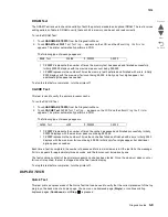
Make sure either letter or A4 size paper is loaded in the default paper source. If the default source only supports
envelopes, then the Quick Test will be printed from Tray 1.
To run the Quick Test:
1.
Touch
DUPLEX TESTS
from the Diagnostics Menu.
2.
Touch
Quick Test
.
3.
Touch
Single
or
Continuous
.
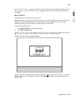
Quick Test Printing...
appears on the LCD.
•
The single Duplex Quick test cannot be canceled.
•
The printer attempts to print the Quick Test Page from the default paper source. If the default paper
source only supports envelopes, then the page is printed from Tray 1.
•
Check the Quick Test Page for the correct registration between the placement of the first scan line on
the front and back side of a duplexed sheet.
The single test stops automatically when a single duplex sheet is printed, and the continuous test continues until
you press
Stop
.
Sensor Test (duplex)
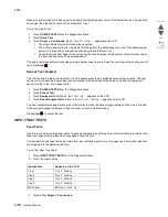
This test is used to determine whether or not the duplex sensors and switches are working correctly. The test
allows you to actuate the duplex input sensor located in the back part of the duplex unit and the duplex exit
sensor located in the return paper path.
1.
Touch
DUPLEX TESTS
from the Diagnostics Menu.
2.
Touch
Sensor Test.
3.
Touch
Duplex wait
and
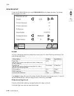
Duplex wait Testing...
appears on the LCD.
4.
Touch
Door B duplex left
and
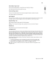
Door B duplex left Testing...
appears on the LCD.
You can manipulate the appropriate area of the printer to make the sensor toggle between “Open” and “Closed”.
If the wrong message is displayed, then the sensor must be malfunctioning.
Press
Stop
to cancel the test.
INPUT TRAY TESTS
Feed Tests
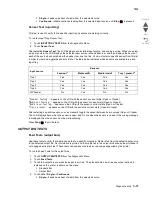
Use this test to observe the paper path of media as it passes through the printer. No information is printed on the
feed test pages since the laser is not engaged during this test.
You can perform the feed test using media from any installed input source. All pages used during the feed test
are dropped into the default output bin.
To run the Input Tray Tests:
1.
Touch
INPUT TRAY TESTS
from the Diagnostics Menu.
2.
Touch the input source.
3.
Touch either
Single
or
Continuous
.
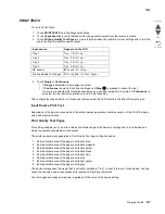
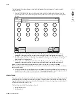
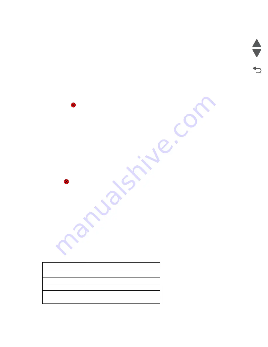
Input source
Appears on the LCD
Tray 1
Tray 1 Feeding...
Tray 2
Tray 2 Feeding...
Tray 3
Tray 3 Feeding...
Tray 4
Tray 4 Feeding...
MP Feeder
MP Feeder Feeding...
Summary of Contents for X945E
Page 20: ...xx Service Manual 7510 Go Back Previous Next ...
Page 25: ...Notices and safety information xxv 7510 Go Back Previous Next ...
Page 26: ...xxvi Service Manual 7510 Go Back Previous Next ...
Page 32: ...xxxii Service Manual 7510 Go Back Previous Next ...
Page 88: ...1 56 Service Manual 7510 Go Back Previous Next TTM theory ...
Page 97: ...General information 1 65 7510 Go Back Previous Next 3TM theory ...
Page 104: ...1 72 Service Manual 7510 Go Back Previous Next 1TM theory ...
Page 111: ...General information 1 79 7510 Go Back Previous Next Duplex ...
Page 432: ...3 52 Service Manual 7510 Go Back Previous Next ...
Page 475: ...Repair information 4 43 7510 Go Back Previous Next E F ...
Page 483: ...Repair information 4 51 7510 Go Back Previous Next Connectors A ...
Page 623: ...Repair information 4 191 7510 Go Back Previous Next ...
Page 653: ...Repair information 4 221 7510 Go Back Previous Next ...
Page 714: ...4 282 Service Manual 7510 Go Back Previous Next ...
Page 715: ...Connector locations 5 1 7510 Go Back Previous Next 5 Connector locations Locations ...
Page 720: ...5 6 Service Manual 7510 Go Back Previous Next Printhead Polygon mirror motor ...
Page 725: ...Connector locations 5 11 7510 Go Back Previous Next ...
Page 726: ...5 12 Service Manual 7510 Go Back Previous Next ...
Page 729: ...Connector locations 5 15 7510 Go Back Previous Next Switch media size Switch TTM media size ...
Page 765: ...Parts catalog 7 31 7510 Go Back Previous Next Assembly 29 Electrical 1 3 5 9 2 10 6 4 8 1 7 ...
Page 770: ...7 36 MFP Service Manual 7510 Go Back Previous Next Assembly 32 Electrical 4 2 1 4 3 5 7 6 8 9 ...
Page 797: ...Parts catalog 7 63 7510 Go Back Previous Next Assembly 50 1TM feed unit assembly 4 3 5 4 1 2 ...
Page 802: ...7 68 MFP Service Manual 7510 Go Back Previous Next Assembly 53 1TM drive and electrical ...
Page 804: ...7 70 MFP Service Manual 7510 Go Back Previous Next Assembly 54 3TM covers 3 5 2 4 1 ...
Page 812: ...7 78 MFP Service Manual 7510 Go Back Previous Next Assembly 58 3TM drive and electrical ...
Page 815: ...Parts catalog 7 81 7510 Go Back Previous Next Assembly 60 TTM media trays 3 5 4 3 7 2 6 8 1 ...
Page 824: ...7 90 MFP Service Manual 7510 Go Back Previous Next Assembly 67 TTM drive and electrical ...
Page 828: ...7 94 MFP Service Manual 7510 Go Back Previous Next ...
Page 836: ...I 8 Service Manual 7510 Go Back Previous Next ...
Page 844: ...I 16 Service Manual 7510 Go Back Previous Next ...

