


3-16
Service Manual
7510
Go Back
Previous
Next
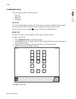
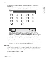
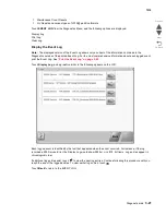
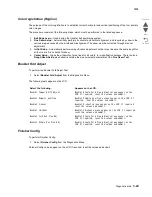
Devices Sensors
Exit Level Sensor
Media Path Sensors
Transfer Belt Sensors
To test any of the displayed sensors, you must manipulate the appropriate area of the printer so the sensor’s
value will toggle to Open or Closed.
If the panel inaccurately displays the sensor’s status, then the sensor must be malfunctioning.
Press
Stop
to cancel the test.
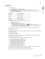
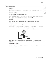
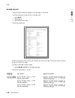
DEVICE TESTS
Quick Disk Test
This test will perform a non-destructive read/write on one block per track on the disk.
To run the Quick Disk Test:
1.
Touch
DEVICE TESTS
from the Diagnostics Menu.
2.
Touch
Quick Disk Test
.
Sensor Name
C PC cartridge present
M PC cartridge present
Y PC cartridge present
K PC cartridge present
Waste toner full
Sensor Name
Standard bin full
Sensor Name
Registration
Fuser exit
Transparency detect
2nd transfer roll retract
Sensor Name
Transfer belt HP
CMY transfer roll retract HP
Transfer belt edge
Transfer belt position detect
Summary of Contents for X945E
Page 20: ...xx Service Manual 7510 Go Back Previous Next ...
Page 25: ...Notices and safety information xxv 7510 Go Back Previous Next ...
Page 26: ...xxvi Service Manual 7510 Go Back Previous Next ...
Page 32: ...xxxii Service Manual 7510 Go Back Previous Next ...
Page 88: ...1 56 Service Manual 7510 Go Back Previous Next TTM theory ...
Page 97: ...General information 1 65 7510 Go Back Previous Next 3TM theory ...
Page 104: ...1 72 Service Manual 7510 Go Back Previous Next 1TM theory ...
Page 111: ...General information 1 79 7510 Go Back Previous Next Duplex ...
Page 432: ...3 52 Service Manual 7510 Go Back Previous Next ...
Page 475: ...Repair information 4 43 7510 Go Back Previous Next E F ...
Page 483: ...Repair information 4 51 7510 Go Back Previous Next Connectors A ...
Page 623: ...Repair information 4 191 7510 Go Back Previous Next ...
Page 653: ...Repair information 4 221 7510 Go Back Previous Next ...
Page 714: ...4 282 Service Manual 7510 Go Back Previous Next ...
Page 715: ...Connector locations 5 1 7510 Go Back Previous Next 5 Connector locations Locations ...
Page 720: ...5 6 Service Manual 7510 Go Back Previous Next Printhead Polygon mirror motor ...
Page 725: ...Connector locations 5 11 7510 Go Back Previous Next ...
Page 726: ...5 12 Service Manual 7510 Go Back Previous Next ...
Page 729: ...Connector locations 5 15 7510 Go Back Previous Next Switch media size Switch TTM media size ...
Page 765: ...Parts catalog 7 31 7510 Go Back Previous Next Assembly 29 Electrical 1 3 5 9 2 10 6 4 8 1 7 ...
Page 770: ...7 36 MFP Service Manual 7510 Go Back Previous Next Assembly 32 Electrical 4 2 1 4 3 5 7 6 8 9 ...
Page 797: ...Parts catalog 7 63 7510 Go Back Previous Next Assembly 50 1TM feed unit assembly 4 3 5 4 1 2 ...
Page 802: ...7 68 MFP Service Manual 7510 Go Back Previous Next Assembly 53 1TM drive and electrical ...
Page 804: ...7 70 MFP Service Manual 7510 Go Back Previous Next Assembly 54 3TM covers 3 5 2 4 1 ...
Page 812: ...7 78 MFP Service Manual 7510 Go Back Previous Next Assembly 58 3TM drive and electrical ...
Page 815: ...Parts catalog 7 81 7510 Go Back Previous Next Assembly 60 TTM media trays 3 5 4 3 7 2 6 8 1 ...
Page 824: ...7 90 MFP Service Manual 7510 Go Back Previous Next Assembly 67 TTM drive and electrical ...
Page 828: ...7 94 MFP Service Manual 7510 Go Back Previous Next ...
Page 836: ...I 8 Service Manual 7510 Go Back Previous Next ...
Page 844: ...I 16 Service Manual 7510 Go Back Previous Next ...


