


General information
1-27
7510
Go Back
Previous
Next
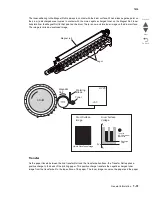
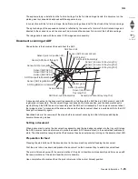
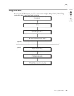
Determination of printhead ready
The printhead goes into ready state after the specified period passes since the reception of the printhead MPA
start signal and the SOS cycle exceeds the reference value.
Printhead reference value
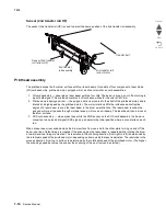
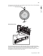
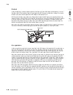
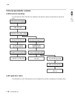
Fuser control
Fuser control method
The on/off control of the main/sub heater lamps is performed based on the fuser control temperature. The fuser
transmits between the five states (warm up, ready, standby, print, and low power) depending on the heat roll
surface temperature or printer conditions.
The fuser temperature control starts when the fuser ready in the AC drive card assembly is turned on after a
preset time period has passed from power on. If a failure occurs, the heater lamps are turned off, the fuser ready
is turned off, and then the fuser temperature control is stopped.
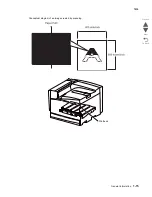
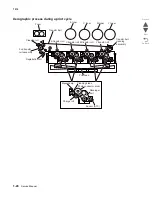
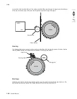
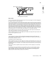
Main/sub heater lamps on/off control
The front and rear thermistors detect the heat roll surface temperature (fuser temperature) to regulate the
temperature at the target control temperature by turning on or off the main/sub heater lamps.
Fuser warm-up
The fuser warm-up starts at the time of power on, interlock open or close, jam reset, or return from the low power
mode, and ends when the ready temperature is attained, when a failure occurs, or when executing diagnosis.
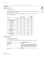
Printhead reference value
Description
Ready reference value
SOS signal interval (equivalent to 98% or more of the rated RPM of the
printhead motor)
Fail reference value
SOS signal interval (less than 98% of the rated rpm of the printhead
motor)
Summary of Contents for X945E
Page 20: ...xx Service Manual 7510 Go Back Previous Next ...
Page 25: ...Notices and safety information xxv 7510 Go Back Previous Next ...
Page 26: ...xxvi Service Manual 7510 Go Back Previous Next ...
Page 32: ...xxxii Service Manual 7510 Go Back Previous Next ...
Page 88: ...1 56 Service Manual 7510 Go Back Previous Next TTM theory ...
Page 97: ...General information 1 65 7510 Go Back Previous Next 3TM theory ...
Page 104: ...1 72 Service Manual 7510 Go Back Previous Next 1TM theory ...
Page 111: ...General information 1 79 7510 Go Back Previous Next Duplex ...
Page 432: ...3 52 Service Manual 7510 Go Back Previous Next ...
Page 475: ...Repair information 4 43 7510 Go Back Previous Next E F ...
Page 483: ...Repair information 4 51 7510 Go Back Previous Next Connectors A ...
Page 623: ...Repair information 4 191 7510 Go Back Previous Next ...
Page 653: ...Repair information 4 221 7510 Go Back Previous Next ...
Page 714: ...4 282 Service Manual 7510 Go Back Previous Next ...
Page 715: ...Connector locations 5 1 7510 Go Back Previous Next 5 Connector locations Locations ...
Page 720: ...5 6 Service Manual 7510 Go Back Previous Next Printhead Polygon mirror motor ...
Page 725: ...Connector locations 5 11 7510 Go Back Previous Next ...
Page 726: ...5 12 Service Manual 7510 Go Back Previous Next ...
Page 729: ...Connector locations 5 15 7510 Go Back Previous Next Switch media size Switch TTM media size ...
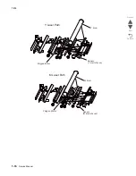
Page 765: ...Parts catalog 7 31 7510 Go Back Previous Next Assembly 29 Electrical 1 3 5 9 2 10 6 4 8 1 7 ...
Page 770: ...7 36 MFP Service Manual 7510 Go Back Previous Next Assembly 32 Electrical 4 2 1 4 3 5 7 6 8 9 ...
Page 797: ...Parts catalog 7 63 7510 Go Back Previous Next Assembly 50 1TM feed unit assembly 4 3 5 4 1 2 ...
Page 802: ...7 68 MFP Service Manual 7510 Go Back Previous Next Assembly 53 1TM drive and electrical ...
Page 804: ...7 70 MFP Service Manual 7510 Go Back Previous Next Assembly 54 3TM covers 3 5 2 4 1 ...
Page 812: ...7 78 MFP Service Manual 7510 Go Back Previous Next Assembly 58 3TM drive and electrical ...
Page 815: ...Parts catalog 7 81 7510 Go Back Previous Next Assembly 60 TTM media trays 3 5 4 3 7 2 6 8 1 ...
Page 824: ...7 90 MFP Service Manual 7510 Go Back Previous Next Assembly 67 TTM drive and electrical ...
Page 828: ...7 94 MFP Service Manual 7510 Go Back Previous Next ...
Page 836: ...I 8 Service Manual 7510 Go Back Previous Next ...
Page 844: ...I 16 Service Manual 7510 Go Back Previous Next ...


