I-4
Service Manual
7510
Go Back
Previous
Next
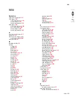
956.00 RIP card assembly processor failure
2-196
956.01 RIP card assembly processor over temperature
failure
2-197
956.02 RIP card assembly cooling fan failure
2-197
956.03 RIP card assembly FPGA failure
2-197
980.00 communication error with 1TM, 3TM, or TTM
assembly
2-198
980.01 HVPS controller communication error
2-198
980.02 communication error between printer and RIP
card assembly
2-199
980.03 communication error with finisher controller card
assembly
2-199
error messages
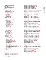
PC cartridge invalid
2-215
PC cartridge not detected
2-215
toner cartridge detection error
2-220
toner cartridge empty
2-219
toner cartridge nearly empty
2-218
1TM, 3TM or TTM left door assembly open
2-200
ADF left cover assembly is open
2-211
ADF maintenance required
2-210
black toner cartridge detection error
2-109
CMY PC cartridge exhausted
2-216
CMY PC cartridges nearly exhausted
2-216
duplex left door assembly open
2-201
incorrect toner cartridge error
2-220
incorrect black toner cartridge error
2-220
K PC cartridge exhausted
2-217
K PC cartridge nearly exhausted
2-217
media size mismatch in width
2-202
,
2-203
no media in the select media tray
2-204
paper is installed (short edge) in the media paper tray
2-205
PC cartridge end of life
2-206
printer front door open
2-206
printer left door open
2-207
printer left lower door open
2-209
scanner unit assembly not detected
2-211
scheduled maintenance required
2-209
,
2-210
standard bin full
2-210
toner cartridge error
2-212
toner cartridge set error
2-212
transfer belt access door open
2-208
tray 1 media size mismatch error
2-221
tray 1 media type mismatch error
2-223
tray 2 media size mismatch error
2-221
tray 2 media type mismatch error
2-224
tray 3 media size mismatch error
2-222
tray 3 media type mismatch error
2-225
tray 4 media size mismatch error
2-223
tray 4 media type mismatch error
2-226
waste toner cartridge full
2-213
waste toner cartridge nearly full
2-214
waste toner cartridge not detected
2-214
ESD-sensitive parts
4-1
exiting Configuration Menu
3-50
exiting Diagnostics Menu
3-34
H
Home button
2-4
,
2-12
Home screen
2-5
buttons
2-5
home screen
status message bar
2-5
I
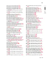
image quality trouble
2-228
blank print (no print)
2-231
faint print (low contrast)
2-229
image quality
2-229
,
2-259
solid black
2-233
troubleshooting
2-228
,
2-258
vertical blank lines (white stripes in media transport
direction)
2-234
image quality troubles
after image
2-245
background (fog)
2-247
color misregistration
2-254
deletions
2-255
horizontal stripes
2-240
horizontal white stripes or bands (side to side direction)
2-236
media damage
2-251
,
2-263
no fuse
2-253
partial lack
2-242
skew
2-249
,
2-262
spots
2-244
,
2-261
vertical stripes
2-238
,
2-260
indicator light
2-3
L
LCD touch-screen features
Attendance message alert
2-12
Menu trail line
2-12
left arrow button
2-9
left scroll decrease button
2-8
light, indicator
2-3
lubrication specification
6-3
M
maintenance scheduled
6-3
memory
1-1
menus
2-264
models
1-1
N
navigation bar
2-5
numeric keypad
2-3
O
operator panel
understanding
2-264
options and features
description
1-3
P
parts catalog
ADF assembly
7-38
ADF covers and components
7-39
ADF document tray
7-51
ADF feeder
7-42
Summary of Contents for X945E
Page 20: ...xx Service Manual 7510 Go Back Previous Next ...
Page 25: ...Notices and safety information xxv 7510 Go Back Previous Next ...
Page 26: ...xxvi Service Manual 7510 Go Back Previous Next ...
Page 32: ...xxxii Service Manual 7510 Go Back Previous Next ...
Page 88: ...1 56 Service Manual 7510 Go Back Previous Next TTM theory ...
Page 97: ...General information 1 65 7510 Go Back Previous Next 3TM theory ...
Page 104: ...1 72 Service Manual 7510 Go Back Previous Next 1TM theory ...
Page 111: ...General information 1 79 7510 Go Back Previous Next Duplex ...
Page 432: ...3 52 Service Manual 7510 Go Back Previous Next ...
Page 475: ...Repair information 4 43 7510 Go Back Previous Next E F ...
Page 483: ...Repair information 4 51 7510 Go Back Previous Next Connectors A ...
Page 623: ...Repair information 4 191 7510 Go Back Previous Next ...
Page 653: ...Repair information 4 221 7510 Go Back Previous Next ...
Page 714: ...4 282 Service Manual 7510 Go Back Previous Next ...
Page 715: ...Connector locations 5 1 7510 Go Back Previous Next 5 Connector locations Locations ...
Page 720: ...5 6 Service Manual 7510 Go Back Previous Next Printhead Polygon mirror motor ...
Page 725: ...Connector locations 5 11 7510 Go Back Previous Next ...
Page 726: ...5 12 Service Manual 7510 Go Back Previous Next ...
Page 729: ...Connector locations 5 15 7510 Go Back Previous Next Switch media size Switch TTM media size ...
Page 765: ...Parts catalog 7 31 7510 Go Back Previous Next Assembly 29 Electrical 1 3 5 9 2 10 6 4 8 1 7 ...
Page 770: ...7 36 MFP Service Manual 7510 Go Back Previous Next Assembly 32 Electrical 4 2 1 4 3 5 7 6 8 9 ...
Page 797: ...Parts catalog 7 63 7510 Go Back Previous Next Assembly 50 1TM feed unit assembly 4 3 5 4 1 2 ...
Page 802: ...7 68 MFP Service Manual 7510 Go Back Previous Next Assembly 53 1TM drive and electrical ...
Page 804: ...7 70 MFP Service Manual 7510 Go Back Previous Next Assembly 54 3TM covers 3 5 2 4 1 ...
Page 812: ...7 78 MFP Service Manual 7510 Go Back Previous Next Assembly 58 3TM drive and electrical ...
Page 815: ...Parts catalog 7 81 7510 Go Back Previous Next Assembly 60 TTM media trays 3 5 4 3 7 2 6 8 1 ...
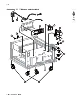
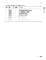
Page 824: ...7 90 MFP Service Manual 7510 Go Back Previous Next Assembly 67 TTM drive and electrical ...
Page 828: ...7 94 MFP Service Manual 7510 Go Back Previous Next ...
Page 836: ...I 8 Service Manual 7510 Go Back Previous Next ...
Page 844: ...I 16 Service Manual 7510 Go Back Previous Next ...

