background image

1-52

Service Manual

7510

Go Back

Previous

Next

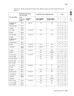
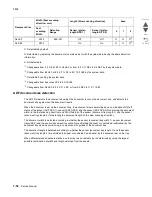
O: Detectable by default.

N: Detectable by replacing the document size marked as O with the system data having the same detection 
information.

X: Not detectable.

*1

: Changeable from 5.5 X 8.5 LEF to A5 LEF, or from 8.5 X 11 SEF to A4 SEF by the system data.

*2

: Changeable from B5 LEF or 8.5 X 11 LEF to 8 X 10.5 LEF by the system data.

*3

: Detectable by setting the system data.

*4:

 Changeable from Executive LEF to 8 X10 LEF.

*5

: Changeable from A4 LEF to 8.5 X 11 LEF, or from A3 SEF to 11 X 17 SEF.

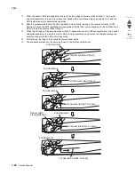
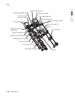
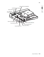
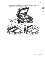
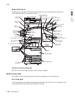
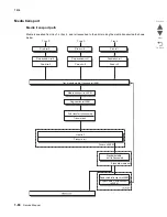
ADF document size detection

The ADF first detects the document size when the document is set on the document tray, and detects the 
document size again when the document travels.

When the document is set on the document tray, the document size is determined by a combination of ON/off 
status of the sensor (ADF APS 1), sensor (ADF APS 2) and the sensor (ADF APS 3) for detecting the document 
width (in the fast scanning direction) and ON/off status of the sensor (document tray length 1) and the sensor 
(document tray length 2) for detecting the document length (in the slow scanning direction). 

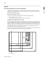
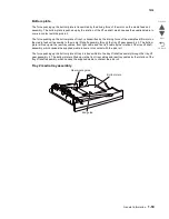
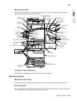
The document width is detected according to whether the sensor (document tray width 1), sensor (document 
tray width 2) and the sensor (document tray width 3) are shielded (blocked) or unshielded (unblocked) by the 
document tray size actuator moving in conjunction with guides of the document tray.

The document length is detected according to whether the sensor (document tray length 1) and the sensor 
(document tray length 2) are shielded (blocked) or unshielded (unblocked) by the document set on the tray.

When different-sized sheets are stacked on the tray, the document size is determined by using the largest 
possible combination of width and length obtained from the sheets.

A4 LEF

297.2

289–307

Off

Off

O

O

O

*5

A3 SEF

297.2

On

On

O

O

O

*5

Document Size

Width (Fast scanning 
direction: mm)

Length (Slow scanning direction)

Area

Fast 
scanning 
Width

Detection 
Range

Sensor (platen 
length APS 1)

Sensor (platen 
length APS 2)

0

1

2

Summary of Contents for X945E

Page 1: ...able of contents Start diagnostics Safety and notices Trademarks Index Lexmark and Lexmark with diamond design are trademarks of Lexmark International Inc registered in the United States and or other countries Revision March 23 2012 ...

Page 2: ... it believes appropriate without incurring any obligation to you References in this publication to products programs or services do not imply that the manufacturer intends to make these available in all countries in which it operates Any reference to a product program or service is not intended to state or imply that only that product program or service may be used Any functionally equivalent prod...

Page 3: ...transport path 1 5 MFP paper path rolls 1 6 MFP sensors 1 7 Functions of main components 1 7 Media tray assembly 1 7 Rear media guide 1 8 End guide 1 8 Bottom plate 1 8 Media tray assembly 1 8 Detection of media size 1 8 Media feed unit assembly 1 8 Media feed lift motor 1 9 Switch media size 1 9 Sensor media out 1 9 Sensor media level 1 9 Sensor feed out 1 9 Multi purpose feeder MPF 1 9 MPF feed ...

Page 4: ...YK toner add motor assembly 1 22 Waste toner agitator motor assembly 1 23 Electrical components and controller 1 23 Switch main power 1 23 Finisher AC output 1 23 Switch printer front door interlock and switch printer left door interlock 1 23 Switch printer left lower door interlock 1 23 Fuser cooling fan 1 23 AC drive card assembly 1 23 5V LVPS card assembly 1 24 24V LVPS card assembly 1 24 CMYK ...

Page 5: ...e lamp PS card assembly 1 45 Lens assembly 1 45 Scanner controller card assembly 1 45 Scanner cooling fan 1 45 ADF 1 46 Sensor ADF tray length 1 1 46 Sensor ADF tray length 2 1 46 Sensor document tray width 1 1 46 Sensor ADF document set 1 46 Pick roll position motor assembly 1 46 Sensor pick roll position HP 1 46 ADF Document Set LED 1 47 Switch ADF left cover interlock 1 47 ADF controller card a...

Page 6: ...ay 2 feed out 1 62 Sensor tray 3 feed out 1 62 Sensor tray 4 feed out 1 62 Tray module media transport roll assembly 1 62 Tray module drive motor 1 63 TTM tray 4 media transport motor 1 63 TTM controller card assembly 1 63 Switch TTM media size 1 64 3TM theory 1 65 Media transport 1 66 Media transport path 1 66 Media transport path 1 67 Functions of main components 1 67 Media tray assembly 1 67 Me...

Page 7: ...or 1 81 Tools required for service 1 82 Acronyms 1 83 Diagnostic information 2 1 Start 2 1 Confirm the installation status 2 2 Power on Reset sequence 2 2 Control panel 2 3 Home screen and Home screen buttons 2 5 Using the LCD touch screen buttons 2 8 Sample screen one 2 8 Information on touch screen buttons 2 8 Sample screen two 2 10 Information on touch screen buttons 2 10 Other touch screen but...

Page 8: ...m 2 95 293 00 Document missing jam 2 95 294 00 Sensor ADF inverter static jam 2 96 294 01 Sensor ADF pre registration late jam side 2 2 97 294 02 Sensor ADF pre registration lag jam inverting 2 99 295 00 Size mismatch jam mix size 2 102 295 01 Size mismatch jam no mix size 2 104 295 02 Invalid combine size jam 2 105 295 03 Too short size jam 2 106 295 04 Too long size jam 2 107 295 05 Mixed size n...

Page 9: ...P late error 2 146 904 01 Transfer belt position failure 2 151 904 02 Sensor transfer belt edge failure 2 156 904 03 Sensor 2nd transfer roll retract HP late error 2 159 904 04 Sensor 2nd transfer roll retract HP lag error 2 160 904 05 Sensor CMY transfer roll retract HP late error 2 162 904 06 Sensor CMY transfer roll retract HP lag error 2 164 904 07 CMY transfer roll retract motor time out 2 16...

Page 10: ...4 953 XX Operator panel assembly NVRAM failure 2 195 954 XX Interconnect card assembly NVRAM failure 2 195 955 XX RIP card assembly NAND CRC failure 2 196 956 00 RIP card assembly processor failure 2 196 956 01 RIP card assembly processor over temperature failure 2 197 956 02 RIP card assembly cooling fan failure 2 197 956 03 RIP card assembly FPGA failure 2 197 980 00 Communication error with 1TM...

Page 11: ...toms 2 228 Image Quality 2 229 Faint print Low contrast 2 229 Blank print no print 2 231 Solid black 2 233 Vertical lines and bands process direction 2 234 Horizontal white stripes or bands side to side direction 2 236 Vertical stripes process direction 2 238 Horizontal stripes side to side direction 2 240 Partial lack 2 242 Spots 2 244 After image 2 245 Background fog 2 247 Skew 2 249 Media damag...

Page 12: ...er 3 19 Engine Setting 1 to 4 3 19 Model Name 3 19 Configuration ID 3 19 EVENT LOG 3 20 Display the Event Log 3 21 Print the Event Log 3 22 Clear the Event Log 3 22 SCANNER TESTS 3 23 ASIC Test 3 23 Feed Test 3 23 Scanner Manual Registration 3 24 Sensor Test Scanner Tests 3 24 Trans Belt HP Fail Clear 3 25 Dev Unit Reset 3 25 Fuser Temp Fail Clear 3 25 ATC SENSOR FAILURE CLEAR 3 25 ENGINE ADJUST 3...

Page 13: ...ce work 4 2 Printer front door assembly removal 4 3 Right cover assembly removal 4 4 Top cover assembly removal 4 4 Rear cover assembly removal 4 5 Rear left middle cover removal 4 6 Rear left upper cover removal 4 7 Printer left lower door assembly removal 4 8 MPF feed unit assembly removal 4 8 Front left cover removal 4 9 Duplex media inverter assembly removal 4 9 Duplex unit assembly removal 4 ...

Page 14: ...removal 4 63 Developer carrier removal and replacement 4 67 Photoconductor PC unit assembly removal 4 71 Transfer belt lift latch assembly removal 4 73 Transfer belt steering motor removal 4 75 CMY erase lamp assembly removal 4 75 K erase lamp assembly removal 4 76 Printhead shutter motor assembly 4 78 Switch printer front door interlock removal 4 79 Sensor printer left lower door interlock remova...

Page 15: ...l 4 118 MPF media out actuator removal 4 118 Sensor MPF media out removal 4 119 MPF pick roll assembly removal 4 119 Media feed lift motor removal 4 120 Switch media size removal 4 121 Scanner removals 4 122 Scanner unit assembly removal 4 122 Platen cushion removal 4 123 Large platen glass removal 4 124 Scanner left cover removal 4 124 Scanner right cover removal 4 125 Scanner top rear cover remo...

Page 16: ...M foot cover removal 4 172 2000 sheet dual input TTM right cover removal 4 173 2000 sheet dual input TTM tray module left cover removal 4 174 2000 sheet dual input TTM rear cover removal 4 174 2000 sheet dual input TTM caster removal 4 174 2000 sheet dual input TTM tray support roll removal 4 175 2000 sheet dual input TTM TTM media tray 4 assembly removal 4 177 2000 sheet dual input TTM TTM media ...

Page 17: ...wer 3TM media feed unit assembly removal tray 3 4 220 3X 500 sheet drawer 3TM media feed unit assembly removal tray 2 4 222 3X 500 sheet drawer 3TM sensor tray 3 feed out removal 4 223 3X 500 sheet drawer 3TM media feed lift motor removal 4 224 3X 500 sheet drawer 3TM one way clutch gear assembly removal 4 225 3X 500 sheet drawer 3TM media out actuator removal 4 226 3X 500 sheet drawer 3TM sensor ...

Page 18: ...etup 4 267 In out setup 4 272 Center setup 4 276 Transfer belt lift mechanism adjustment 4 277 Connector locations 5 1 Locations 5 1 5 11 Preventive maintenance 6 1 Safety inspection guide 6 1 Scheduled maintenance 6 3 Parts catalog 7 1 How to use this parts catalog 7 1 Assembly 1 Covers 1 7 2 Assembly 2 Covers 2 7 3 Assembly 3 Covers 3 7 4 Assembly 4 PC cartridge and developer drive 7 5 Assembly ...

Page 19: ...embly 44 Control panel and platen glass 7 55 Assembly 45 Scanner electrical 7 57 Assembly 46 Scanner optics 7 58 Assembly 47 Carriage cable and motor 7 60 Assembly 48 MFP rack 7 61 Assembly 49 1TM covers 7 62 Assembly 50 1TM feed unit assembly 7 63 Assembly 51 1TM media feed unit 7 65 Assembly 52 1TM left door 7 67 Assembly 53 1TM drive and electrical 7 68 Assembly 54 3TM covers 7 70 Assembly 55 3...

Page 20: ...xx Service Manual 7510 Go Back Previous Next ...

Page 21: ...tzer oder bei ordnungsgemäßer Wartung durch den Kundendienst Laserbestrahlung die Klasse I übersteigen würde Menschen keinesfalls erreicht Avis relatif à l utilisation de laser Pour les Etats Unis cette imprimante est certifiée conforme aux provisions DHHS 21 CFR alinéa J concernant les produits laser de Classe I 1 Pour les autres pays cette imprimante répond aux normes IEC 60825 1 relatives aux p...

Page 22: ...seneto de potássio de 5 milliwatts operando numa faixa de comprimento de onda entre 770 e 795 nanómetros O sistema e a impressora laser foram concebidos de forma a nunca existir qualquer possiblidade de acesso humano a radiação laser superior a um nível de Classe I durante a operação normal a manutenção feita pelo utilizador ou condições de assistência prescritas Laserinformatie De printer voldoet...

Page 23: ...ukitus ohitettaessa olet alttiina näkymättömälle lasersäteilylle Älä katso säteeseen VARNING Osynlig laserstrålning när denna del är öppnad och spärren är urkopplad Betrakta ej strålen Laser notis Denna skrivare är i USA certifierad att motsvara kraven i DHHS 21 CFR underparagraf J för laserprodukter av Klass I 1 I andra länder uppfyller skrivaren kraven för laserprodukter av Klass I enligt kraven...

Page 24: ...its d IEC 60825 1 Els productes làser de classe I no es consideren perillosos Aquesta impressora conté un làser de classe IIIb 3b d arseniür de gal li nominalment de 5 mil liwats i funciona a la regió de longitud d ona de 770 795 nanòmetres El sistema làser i la impressora han sigut concebuts de manera que mai hi hagi exposició a la radiació làser per sobre d un nivell de classe I durant una opera...

Page 25: ...Notices and safety information xxv 7510 Go Back Previous Next ...

Page 26: ...xxvi Service Manual 7510 Go Back Previous Next ...

Page 27: ...s Les consignes d entretien et de réparation de ce produit s adressent uniquement à un personnel de maintenance qualifié Le démontage et l entretien de ce produit pouvant présenter certains risques électriques le personnel d entretien qualifié devra prendre toutes les précautions nécessaires ATTENTION Ce symbole indique la présence d une tension dangereuse dans la partie du produit sur laquelle vo...

Page 28: ...mación sobre el mantenimiento de este producto está dirigida exclusivamente al personal cualificado de mantenimiento Existe mayor riesgo de descarga eléctrica y de daños personales durante el desmontaje y la reparación de la máquina El personal cualificado debe ser consciente de este peligro y tomar las precauciones necesarias PRECAUCIÓN este símbolo indica que el voltaje de la parte del equipo co...

Page 29: ...d aquest producte està orientada exclusivament a professionals i no està destinada a ningú que no ho sigui El risc de xoc elèctric i de danys personals pot augmentar durant el procés de desmuntatge i de servei d aquest producte El personal professional ha d estar ne assabentat i prendre les mesures convenients PRECAUCIÓ aquest símbol indica que el voltatge de la part de l equip amb la qual esteu t...

Page 30: ...ifications and recommendations to prevent problems 7 Parts catalog contains illustrations and part numbers for individual FRUs Appendix A contains service tips and information Appendix B contains representative print samples Change history Revision date Updates 2012 03 23 Added PN 40X8459 for the USB connector assembly in Control panel and platen glass on page 7 56 2012 02 09 Added warning with sy...

Page 31: ...Previous Click to move the document view backward by one page Next Click to move the document view forward by one page Go Back Click to return to the last page viewed CAUTION A caution identifies something that might cause a servicer harm CAUTION This type of caution indicates there is a danger from hazardous voltage in the area of the product where you are working Unplug the product before you be...

Page 32: ...xxxii Service Manual 7510 Go Back Previous Next ...

Page 33: ...were made in accordance with ISO 7779 and reported in conformance with ISO 9296 Environment Connectivity Standard USB and internet Optional parallel and serial Size and weight without finisher Size H x W x D 42 x 27 x 25 in 1153 x 660 x 810 mm Weight 383 lb 174 kg Specifications Mode Sound pressure level dBA Sound power level Bels Printing 52 6 9 Copying 53 7 2 Scanning Standby mode 54 32 7 0 Spec...

Page 34: ...ximum 600 x 600 dpi Optical resolution ADF color Maximum 600 x 300 dpi Document capacity 75 sheets 80 g m2 bond Media weight Media weight Maximum 32 lb 128g m2 Minimum 16 lb 38 g m2 50 g m2 for duplex mode Speed maximum Letter A4 long edge fed Mono up to 45 SPM Color up to 45 SPM Scan area ADF Maximum 11 7 x 17 inches 297 x 432 mm Minimum 5 5 x 8 25 inches 139 7 x 210 mm Enlargement reduction capa...

Page 35: ...trical or cabling connections such as the power cord or options and features during a lightning storm Basic model The following illustration shows a printer with its base features Duplex unit Multipurpose feeder MPF Tray 1 and tray 2 500 sheet trays Tray 3 and tray 4 850 1150 sheet dual input tray TTM Operator panel ADF ...

Page 36: ...ustration shows a fully configured printer Items denoted with an asterisk are options Finisher Bridge unit Used in conjunction with finisher Duplex unit Multipurpose feeder MPF Tray 1 and tray 2 500 sheet trays Tray 3 and tray 4 850 1150 sheet dual input tray TTM Operator panel ADF ...

Page 37: ...unit ASM Media feed unit ASM Pick roll Pick roll Separation roll Separation roll Feed roll Media transport roll ASM Tray 1 Tray 2 Feed roll Registration roll ASM 2nd Transfer roll ASM Transfer belt Heat roll Pressure belt Fuser unit ASM Fuser media exit roll assembly Duplex media transportrollASM Standard media exit Media feed unit ASM Pick roll Separation roll Tray 3 Feed roll Media feed unit ASM...

Page 38: ...t assembly included with finisher Tray module transport roll assembly TTM Pick roll Feed roll Separation roll Registration roll assembly Tray module transport roll assembly MPF pick roll Tray 4 transport roll assembly Finisher media entrance roll assembly Upper media exit roll assembly Upper media transport roll assembly Buffer roll assembly Lower media exit roll assembly Booklet media transport r...

Page 39: ...ray 1 feed out Sensor registration Sensor bridge unit media entrance Sensor bridge unit media exit Sensor standard bin media full 3TM optional Tray 2 Tray 3 Tray 4 Sensor tray 3 feed out Sensor tray 2 feed out Sensor tray 4 feed out Tray 2 1TM optional Sensor tray 2 feed out Tray 2 Tray 3 Tray 4 TTM Sensor tray 3 feed out Sensor tray 2 feed out Sensor tray 4 feed out Fuser Sensor upper media bin f...

Page 40: ...y is transmitted to the switch media size by moving these guides The media size is detected by the on off information of these switches Media feed unit assembly Since tray 1 and tray 2 are functionally equivalent in terms of the switch media size sensor media out sensor media level and sensor pre feed only the components of one tray are described here The media feed unit assembly is a mechanical u...

Page 41: ...ia out The sensor light is transmitted When the sensing area is blocked media is present the signal is off Sensor media level This sensor detects by the actuator position whether media in the media tray assembly is lifted When the flag of the actuator unblocks the sensing area of the sensor media level the sensor detects that the media has been lifted Sensor feed out This sensor detects the media ...

Page 42: ...sor MPF media out detects whether media is present on the MPF Sensor MPF media width The MPF side guides detects the width length in the main scanning direction of media on the MPF Media size The following table details the standard paper and envelope sizes supported by the Lexmark X945e MFPs and options Media Width Length A4 210 mm 297 mm A5 148 mm 210 mm A3 297 mm 420 mm JIS B5 182 mm 257 mm JIS...

Page 43: ... Media transport roll assembly The media transport roll assembly feeds paper from tray 2 tray 3 and tray 4 toward the registration roll assembly Registration roll assembly Statement 5 5 inches 8 5 inches Universal MPF only 140 to 297 mm 5 5 to 11 7 inches 105 to 305 mm 4 1 to 12 inches 98 4 to 432 mm 3 9 to 17 inches 148 to 482 mm 5 8 to 19 inches 7 3 4 Envelope 98 4 mm 3 875 inches 190 5 mm 7 5 i...

Page 44: ...his motor is used to rotate the transfer belt Transfer belt cleaning assembly This assembly is used to remove residual toner images from the transfer belt after 2nd transfer and before the next print cycle Registration clutch Sensor transparency detect Sensor registration Media transport roll assembly Transfer belt steering motor Transfer belt drive motor Transfer belt cleaning assembly 1st transf...

Page 45: ...ace and CMY drums Transfer belt steering motor This motor is used to ensure that the transfer belt is properly tracking If the transfer belt starts to track off center then the transfer belt steering motor will activate to keep the transfer belt centered and tracking properly 2nd transfer roll assembly The 2nd transfer roll assembly applies positive charges to the rear surface of the media when th...

Page 46: ...aches the polygon mirror as it passes through multiple lenses mirrors and windows The laser beam then arrives at the drum surface 3 SOS card assembly when a laser beam hits the SOS sensor on the SOS card assembly the beam is converted to an electrical signal SOS signal and detects the initial position where a scan starts on each line When a laser beam is scanned across the drum surface from one en...

Page 47: ...General information 1 15 7510 Go Back Previous Next Conceptual diagram of an image created by scanning Printhead ...

Page 48: ...1 16 Service Manual 7510 Go Back Previous Next Y Laser Path Polygon Mirror Y drum Sensor Y start of scan M Laser Path Polygon Mirror M drum Sensor M start of scan ...

Page 49: ...ty the shutter stays closed except when laser beams are written onto the drums The printhead shutter motor assembly is used to prevent contamination from obstructing the printhead slit glasses The printhead shutters for yellow magenta cyan and black are opened or closed simultaneously by the printhead shutter motor assembly C Laser Path C drum Sensor C start of scan Polygon Mirror K Laser Path K d...

Page 50: ...ll is a hollow metal tube with a coated surface This tube is heated by the inner heater lamp The heat is applied to the media passing between the heat roll and pressure roll fusing the toner on the media Fuser cooling fan Heat roll Sensor fuser exit Pressure belt Thumb screws ...

Page 51: ...ature the thermostat cuts off the circuits of the main heater lamp and sub heater lamp Front thermistor The front thermistor monitors the surface temperature of the media feed portion of the heat roll to control on off of the main heater lamp and sub heater lamp Rear thermistor The rear thermistor monitors the surface temperature at the rear side of the heat roll to switch the heater lamp to on Fu...

Page 52: ...iverter gate The duplex diverter gate switches the media transport path When the duplex diverter gate is lifted media is fed to the standard bin When it is lowered media is fed to the duplex Drive K developer transport drive motor assembly The K developer transport drive motor is a DC motor that drives the K developer unit assembly registration roll 2nd transfer roll fuser and standard media exit ...

Page 53: ...es the MPF unit assembly and media transport roll CMYK PC cartridge drive motor assembly The CMYK PC cartridge drive motor assembly uses dual DC brushless motors that drive the four drums in the four PC cartridges K developer transport drive motor assembly MPF transport drive motor K drive motor CMY drive motor ...

Page 54: ...semblies K developer clutch This clutch is used to engage the K developer unit assembly and is driven by the K developer transfer drive motor assembly CMYK toner add motor assembly K developer clutch CMY developer drive motor assembly Y toner add motor Y toner add assembly M toner add motor M toner add assembly C toner add motor C toner add assembly K toner add motor K toner add assembly ...

Page 55: ...rlock and switch printer left door interlock The switch is a safety switch to cut off a 24 VDC power supply from the LVPS card assembly to the high volt power supply HVPS card assembly printer engine card assembly and to the dual motor assembly while the printer front door assembly and the printer left door assembly are open Switch printer left lower door interlock The switch left lower door inter...

Page 56: ...er roll HVPS card assembly generates AC power and feeds it to the CMYK transfer rolls inside the transfer belt unit assembly Developer roll HVPS card assembly The HVPS card assembly generates AC power and feeds it to the four developer rolls the transfer belt unit assembly and the 2nd transfer roll assembly Charge roll HVPS card assembly The HVPS card assembly generates AC power and feeds it to th...

Page 57: ...ation based on the communication with the RIP card assembly and on sensor switch information It also controls many of the drive motors clutches and solenoids RIP card assembly The RIP card assembly connected to the printer engine card assembly controls the entire system as well as the printhead operations Rear Fuser cooling fan Rear upper cooling fan 24V LVPS cooling fan AC drive card Assembly Rea...

Page 58: ...S W5 No media tray assembly Off Off Off Off Off 5 5 X 8 5 SEF A5 SEF Off Off On Off Off B5 SEF Off Off On On On 8 5 X 13 SEF Off On Off On Off 8 5 X 14 SEF Off On Off On On A4 SEF Off On On Off Off 8 5 X 11 SEF Off On On Off On A4 LEF On Off On Off Off A3 SEF On Off On On Off B5 LEF executive LEF On On Off Off On 8K SEF TFX GCO On On Off On Off B4 SEF On On Off On On 8 5 X 11 LEF On On On Off Off ...

Page 59: ... preset time period has passed from power on If a failure occurs the heater lamps are turned off the fuser ready is turned off and then the fuser temperature control is stopped Main sub heater lamps on off control The front and rear thermistors detect the heat roll surface temperature fuser temperature to regulate the temperature at the target control temperature by turning on or off the main sub ...

Page 60: ...toner C toner M toner Y toner 2nd transfer roll assembly Printhead Transfer belt Fuser Cleaning roll Transfer belt cleaning assembly Cleaning blade Photo conductor drum Charge roll Sensor ATC Erase Lamp Developer unit K transfer roll C transfer roll M transfer roll Y transfer roll Registration roll ...

Page 61: ...ge The charge roll is a conductive roll that is positioned slightly above the surface of the drum The HVPS supplies the charge roll with two voltages a negative DC charge voltage and an AC discharge voltage that is used for electrically cleaning the drum HVPS VDC VDC Ground Conductive Tube Photoconductive Surface 0V VDC value DRUM Drum Surface Voltage Drum Surface Image Ground Charge roll HVPS VDC...

Page 62: ...e to the Magnetic Roll The Metering Blade spreads the toner into a very thin layer on the Magnetic Roll Friction between the Magnetic Roll and the CM Blade generates a small electrical charge that is transferred to the toner The surface of the Magnetic Roll is made up of a thin sheet of conductive material The HVPS supplies the Magnetic Roll with two voltages a DC voltage and an AC voltage The DC ...

Page 63: ...rum surface The image is called a developed image Transfer As the paper travels between the 2nd transfer Roll and the transfer belt surface the Transfer Roll applies a positive charge to the back of the printing paper This positive charge transfers the negative charged toner image from the transfer belt to the top surface of the paper The toner image is now on the paper and the paper Magnet roll A...

Page 64: ...Blade removes any toner that remains on the drum after the transfer process The toner that the Cleaning Blade removes is collected inside the sealed PC Cartridge and reused Discharge At both the start and the end of each individual printer cycle the erase lamps electrically clean the drum The light emitted removes any residual DC charge that was left from the previous print cycle Sheet of paper HV...

Page 65: ...nsor that detects a pre placed toner patch and image on the transfer belt and outputs pulses when the central line of the patch image aligns with the central line of the detector The sensor outputs pulses at the timing the patch image passes the sensor Therefore observing changes of intervals at which pulses are output leads to color mis registration detection If no color mis registration occurs p...

Page 66: ... document at a constant speed over the specified position scan position where the carriage full half rate carriage of the scanner unit assembly is fixed Document scanning at platen Shown below is the operational overview of document scanning at the platen The full rate carriage and half rate carriage travel to read the document ADF Scan position Platen registration point Full rate carriage CCD Sen...

Page 67: ...efore document scanning and that of simplex and duplex document scanning modes Setting a document When a document is set on the document tray assembly and the lead edge is pushed into the tray until it stops the ADF document set actuator moves to place the sensor ADF document set in the unshielded unblocked state Then the machine recognizes that the document has been set properly turning on the do...

Page 68: ... lead edge of the document sheet is fed from the ADF registration roll assembly to the scan feed reference position Wait Position located upstream from the scan position where the document stops Thus registration of the lead edge of the document is performed When the document sheet is fed to the ADF transport roll assembly the ADF feed motor assembly changes its rotational direction to the normal ...

Page 69: ...egistration the ADF feed motor assembly stops When the predetermined period of time has elapsed since the document sheet passed through the sensor ADF inverter the ADF registration motor stops Inversion In the inversion step the document sheet is inverted at the inverter gate and fed to the ADF transport roll assembly again By thrusting the document sheet against the ADF transport roll assembly at...

Page 70: ...t is fed at the feed speed corresponding to the selected magnification and the image on it is scanned with the exposure lamp at the scan position see Scan control 4 As the image is scanned the document sheet is fed and ejected by the ADF feed out roll assembly and ADF exit roll assembly that are driven by the ADF registration motor turning in the reverse direction CCW direction 5 When the trail ed...

Page 71: ...ter solenoid assembly is turned on to release the nipped ADF exit roll assembly and exit pinch roll If these rolls are not released the lead edge of the document sheet Side 2 reaches the ADF exit roll assembly before the trail edge of the document sheet Side 2 leaves the ADF exit roll assembly when the document sheet Side 2 is long in the slow scanning direction 6 The document sheet Side 2 is fed ...

Page 72: ... in the exit direction in order to feed the document sheet Side 1 13 When the trail edge of the document sheet Side 1 passes the sensor ADF pre registration the inverter solenoid assembly is turned off to nip the ADF exit roll assembly and exit pinch roll thereby ejecting the document sheet with the ADF exit roll assembly 14 At this timing the feed of the second document sheet starts 15 The subseq...

Page 73: ...e from the document set on the scanner unit assembly or ADF goes through the following components before it is printed at the Engine section Lens CCD image sensor Scanner controller card assembly Scanner Engine RIP card assembly Printhead assembly PC cartridge assembly drum Document ...

Page 74: ...tional force of the ADF registration motor is transferred to each document feeding roll as shown below ADF feed motor assembly ADF drive belt Feed drive rear pulley 14 32 37 Transport roll drive belt Feed pick drive gear 20T Transport roll drive gear pulley 20 50T Feed pick drive shaft assembly Transport roll drive gear 20T Feed roll drive gear 26T Transport roll assembly Feed roll Pick roll idler...

Page 75: ...n motor Registration roll drive belt Registration drive gear pulley 21 54T Registration drive belt Exit feed out drive pulley 25 28 Registration roll drive gear 28T Exit roll drive belt Feed out roll assembly Registration roll assembly Exit roll drive pulley 20T Exit roll assembly ...

Page 76: ...ll drive gear 26T ADF feed motor assembly Feed pick drive gear 20T Feed drive gear pulley14 32 37T Transport roll drive gear pulley 20 50T ADF registration motor Registration main drive pulley 21 54T Transport roll drive gear 20T Registration roll drive pulley 28T Exit feed out drive pulley 25 28 Transport roll assembly Registration roll assembly Feed out roll assembly ...

Page 77: ...ize detection Scanner drive motor assembly A stepping motor that drives the full rate carriage and the half rate carriage Sensor scanner HP A sensor that detects the HP position of the full rate carriage The rear portion of the full rate carriage frame functions as an actuator that shields the sensor scanner HP for detection Scanner exposure lamp A xenon lamp to which the document is exposed Expos...

Page 78: ...ion of the tray on which the document is set Sensor ADF document set A sensor that detects the presence or absence of a document on the ADF document tray Presence Beam is unshielded unblocked Absence Beam is shielded blocked Pick roll position motor assembly A stepping motor that moves the pick roll vertically Sensor pick roll position HP A sensor that detects the home position of the pick roll Le...

Page 79: ...r ADF APS 3 These are sensors that detect the fast scanning directional width of the moving document Sensor ADF sheet through The ADF sensor ADF sheet through is installed immediately downstream from the Feed roll to detect completion of document feed document is present shielded blocked document is absent unshielded unblocked Sensor ADF pre registration Sensor document tray width 2 Sensor documen...

Page 80: ...F feed motor assembly The feed motor assembly is a stepping motor that rotates the pick roll and feed roll in the reverse direction CCW direction and rotates the ADF transport roll assembly in the normal direction CW direction When this motor rotates in the reverse direction the ADF transport roll assembly stops ADF registration motor The registration motor is a stepping motor that rotates the ADF...

Page 81: ...ack Previous Next Sensor ADF pre registration ADF feed motor assembly Sensor sheet through ADF registration motor Sensor ADF registration Sensor ADF inverter Sensor ADF APS 1 Sensor ADF APS 2 Sensor ADF APS 3 Inverter solenoid assembly ...

Page 82: ... the document sheet is detected in millimeters with the CCD image sensor to determine the size in the fast scanning direction With respect to a pair of documents whose sizes in the fast scanning direction are the same the document size is determined by detecting paper presence absence at the positions of sensor platen length APS 1 and sensor platen length APS 2 e g A4LEF vs A3SEF 8 5x11SEF vs 8 5x...

Page 83: ...O X A5 SEF 148 0 O X O Japanese Post Card LEF 148 0 X X N Post Card LEF 152 4 N N X B5 SEF 182 0 163 188 On Off O X O 16kai SEF 194 0 195 0 188 202 On Off Off X X X 3 A5 LEF 210 0 202 213 Off Off O X 3 O A4 SEF 210 0 On On Off O X 3 O 5 5 X 8 5 LEF 215 9 213 226 Off Off O 1 O X 3 8 5 X 11 SEF 215 9 On Off O 1 O X 3 8 5 X 12 4 SEF 215 9 On On N N X 8 5 X 13 SEF 215 9 O N X 8 5X 14 SEF 215 9 N O X 8...

Page 84: ...cument width in the fast scanning direction and ON off status of the sensor document tray length 1 and the sensor document tray length 2 for detecting the document length in the slow scanning direction The document width is detected according to whether the sensor document tray width 1 sensor document tray width 2 and the sensor document tray width 3 are shielded blocked or unshielded unblocked by...

Page 85: ...fied by the same given detection information are defined on an area by area basis Each area is to be set in the system data ADF side 1 ADF side 2 Le xm ar k X0 00 Qu ic k Te st De vic e Inf orm ati on MA RG IN SE TT ING S Flatbed Leading edges Lexmark X000 Quick Test Device Information MARGIN ...

Page 86: ... see Pre registration until its tail end passes through the sensor ADF sheet through Document scanning steps Document Size Width Fast scanning direction Sensor document tray width Length Slow scanning direction Sensor document tray length Area 1 2 3 1 2 0 1 2 5 5 X 8 5 SEF Off Off Off On Off X O X A5 SEF O X O B5 SEF Off Off Off On Off X X O 8 X 10 SEF X O X 8 X 10 5 SEF O X X A5 LEF Off On Off Of...

Page 87: ...black level adjustment of the image AOC is performed at initialization Shading compensation Shading compensation is a function that compensates for pixel to pixel sensitivity variation of the CCD image sensor and pixel to pixel output variation of the CCD image sensor that is caused by illumination non uniformity in the fast scanning direction of the optical system Shading compensation is performe...

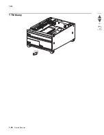
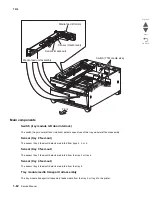
Page 88: ...1 56 Service Manual 7510 Go Back Previous Next TTM theory ...

Page 89: ...Pick roll Pick roll Separation roll Separation roll Feed roll Transfer belt 2nd transfer roll assembly Heat roll Pressure roll Fuser unit ASM Standard media exit roll assembly Duplex media transportrollASM Duplex media Center transport rollASM Tray 3 Tray 4 Feed roll Tray module media Transport roll ASM Media transport roll ASM Registration roll ASM Standard media exit Pick roll Separation roll Fe...

Page 90: ...edia transport roll assembly Tray 2 Tray 3 Tray 4 ADF and Scanner MPF Tray 1 Tray 2 Tray 3 Tray 4 3TM optional Finisher optional Booklet maker unit optional Standard media exit roll assembly Fuser exit roll assembly Duplex media transport roll assembly 2nd transfer roll assembly Bridge unit assembly included with finisher Tray module transport roll assembly TTM Pick roll Feed roll Separation roll ...

Page 91: ... to the media lift shaft assembly through the tray lift gear assembly 3 The bottom plate is lifted up via the rear tray cables front right cable and front left cable by the rotation of the tray lift shaft assembly which causes the supplied media to come into contact with the pick roll The force pushing up the bottom plate of tray 4 is transmitted to the tray lift shaft assembly through the tray li...

Page 92: ...1 60 Service Manual 7510 Go Back Previous Next Tray 3 or 4 media tray assembly Rear lift cables Rear media guide Bottom plate F R lift cable F L lift cable ...

Page 93: ... rotates forward to drive the pick roll When lifting the bottom plate it rotates in reverse to drive the tray module gears to turn the lift up shaft Switch media size This switch media size sets the size of media supplied from each media tray a Switch TTM media size The switch TTM media size switches the setting of the size of media supplied from each media tray assembly A signal indicating the se...

Page 94: ...cts media fed from trays 2 3 or 4 Sensor tray 3 feed out The sensor tray 3 feed out detects media fed from the tray 3 or tray 4 Sensor tray 4 feed out The sensor tray 4 feed out detects media fed from the tray 4 Tray module media transport roll assembly The tray module transport roll assembly feeds media from the tray 3 or tray 4 to the printer Front Switch TTM media size Media feed lift motor Sen...

Page 95: ...t door assembly TTM controller card assembly The TTM controller card assembly which contains a CPU controls media feed in the tandem tray module upon receiving a command from the upper printer engine card assembly and sensor switch information Switch TTM media size Switch tray module interlock TTM controller card assembly Tray module drive motor TTM tray 4 media transport drive motor Front Sensor ...

Page 96: ...tes of the switches on the switch TTM media size corresponding to the media sizes of the media tray assembly Note The switches TTM media size are denoted by S W1 and S W3 respectively from the left side Media Size Analog switch S W1 S W3 No Tray Off Off B5L 7 25 x 10 5 L Off On 8 5 x 11 L On Off A4L On On ...

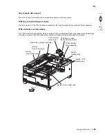
Page 97: ...General information 1 65 7510 Go Back Previous Next 3TM theory ...

Page 98: ...oll Pick roll Separation roll Separation roll Feed roll Transfer belt 2nd transfer roll assembly Heat roll Pressure roll Fuser unit ASM Standard media exit roll assembly Duplex media transportrollASM Duplex media Center transport rollASM Tray 3 Tray 4 Feed roll Tray module media Transport roll ASM Media transport roll ASM Registration roll ASM Standard media exit Pick roll Separation roll Feed rol...

Page 99: ...y 2 1TM optional Media transport roll assembly Tray 2 Tray 3 Tray 4 ADF and Scanner MPF Tray 1 Tray 2 Tray 3 Tray 4 3TM optional Finisher optional Booklet maker unit optional Standard media exit roll assembly Fuser exit roll assembly Duplex media transport roll assembly 2nd transfer roll assembly Bridge unit assembly included with finisher Tray module transport roll assembly TTM Pick roll Feed rol...

Page 100: ...es to feed media When the pick roll picks up sheets of media and the remaining media decreases the media level actuator of the sensor media level lowers accordingly Media feed lift motor The media feed lift motor is activated to feed media and to lift the bottom plate While feeding media it rotates forward to drive the pick roll When lifting the bottom plate it rotates in reverse to drive the tray...

Page 101: ...fted Main components Switch tray module left door interlock The switch tray module left door interlock detects open close of the tray module left door assembly Sensor tray 2 feed out The sensor tray 2 feed out detects media fed from trays 2 3 or 4 Sensor tray 3 feed out The sensor tray 3 feed out detects media fed from the tray 3 or tray 4 Sensor tray 4 feed out The sensor tray 4 feed out detects ...

Page 102: ...rinter Tray module drive motor This motor is used to drive the media transport mechanism in the tray module 3TM controller card assembly The 3TM controller card assembly which contains a CPU controls media feed in the tandem tray module upon receiving a command from the upper printer engine card assembly and sensor switch information ...

Page 103: ...f states of the switches on the switch media size corresponding to the media sizes of the media tray assembly Note The switches media size are denoted by S W1 and S W3 respectively from the left side Media Size Analog switch S W1 S W3 No Tray Off Off B5L 7 25 x 10 5 L Off On 8 5 x 11 L On Off A4L On On ...

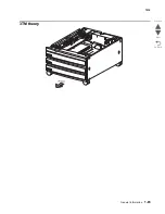
Page 104: ...1 72 Service Manual 7510 Go Back Previous Next 1TM theory ...

Page 105: ...k roll Pick roll Separation roll Separation roll Feed roll Transfer belt 2nd transfer roll assembly Heat roll Pressure roll Fuser unit ASM Standard media exit roll assembly Duplex media transportrollASM Duplex media Center transport rollASM Tray 3 Tray 4 Feed roll Tray module media Transport roll ASM Media transport roll ASM Registration roll ASM Standard media exit Pick roll Separation roll Feed ...

Page 106: ... Media transport roll assembly Tray 2 Tray 3 Tray 4 ADF and Scanner MPF Tray 1 Tray 2 Tray 3 Tray 4 3TM optional Finisher optional Booklet maker unit optional Standard media exit roll assembly Fuser exit roll assembly Duplex media transport roll assembly 2nd transfer roll assembly Bridge unit assembly included with finisher Tray module transport roll assembly TTM Pick roll Feed roll Separation rol...

Page 107: ...a from the media tray assembly to the printer The driving force from the media feed lift motor on the media feed unit assembly is transmitted to the three roll assemblies to feed media When the pick roll picks up sheets of media and the remaining media decreases the media level actuator of the sensor media level lowers accordingly Media feed lift motor The media feed lift motor is activated to fee...

Page 108: ... out actuator that has stayed in the sensor media out sensing area leaves there Thus the light of the sensor is transmitted When the sensing area is blocked media is present the signal turns off Sensor media level This sensor detects by the actuator position whether media in the media tray assembly is lifted When the flag of the actuator leaves the sensor media level sensing area the sensor detect...

Page 109: ...he tray module transport roll assembly feeds media from the tray 2 Tray module drive motor This motor is used to drive the media transport mechanism in the tray module 1TM controller card assembly The 1TM controller card assembly which contains a CPU controls media feed in the 1TM upon receiving a command from the upper printer engine card assembly and sensor switch information ...

Page 110: ...tates of the switches on the switch media size corresponding to the media sizes of the media tray assembly Note The switches media size are denoted by S W1 and S W3 respectively from the left side Media Size Analog switch S W1 S W3 No Tray Off Off B5L 7 25 x 10 5 L Off On 8 5 x 11 L On Off A4L On On ...

Page 111: ...General information 1 79 7510 Go Back Previous Next Duplex ...

Page 112: ...erlock detects open close of the left door Sensor duplex wait The sensor duplex wait detects whether media is remaining in the duplex Duplex media transport roll assembly The two duplex media transport roll assemblies and the duplex media center transport roll assembly re feeds the media printed on the front side through the duplex to print on the rear side Inverter reverse clutch Inverter forward...

Page 113: ...sor switch information Duplex drive motor The duplex drive motor transmits driving force to the two duplex media transport roll assemblies and the duplex media center transport roll assembly middle that feeds media Inverter reverse clutch Inverter forward clutch Standard media exit roll assembly Duplex diverter solenoid Sensor duplex wait Switch duplex left door interlock Duplex media transport ro...

Page 114: ...netic 2 Phillips screwdriver magnetic 2 Phillips screwdriver magnetic short blade Needle nose pliers Diagonal side cutters Spring hook Analog or digital multi meter Parallel wrap plug 1319128 Twinax serial debug cable 1381963 Coax serial debug cable 1381964 5 5 mm hexdriver magnetic Color toner vacuum Fine incremental ruler ...

Page 115: ... High Capacity Feeder HVPS High Voltage Power Supply LASER Light Amplification by Stimulated Emission of Radiation LCD Liquid Crystal Display LD Laser Diode LED Light Emitting Diode LEF Long Edge Feed LVPS Low Voltage Power Supply MPF Multi Purpose Feeder MS Microswitch NVM Nonvolatile Memory NVRAM Nonvolatile Random Access Memory OEM Original Equipment Manufacturer OPT Optical Sensor PC Photocond...

Page 116: ... Manual 7510 Go Back Previous Next SRAM Static Random Access Memory TTM Tandem Tray Module TVOC Total Volatile Organic Compound UPR Used Parts Return V Volts V ac Volts alternating current V dc Volts direct current ...

Page 117: ...t level support for assistance CAUTION Unplug the power cord from the electrical outlet before you connect or disconnect any cable electronic board or assembly CAUTION If the printer is kept on never touch the conductive parts if not specifically required The power switch and inlet of the low voltage power supply card LVPS card assembly is live even while the power supply is cut off Never touch th...

Page 118: ...s generated The printer is not installed in direct sun The printer is installed on a level and stable surface Media meets specifications and is installed properly Customer maintenance parts have been replaced at the specified intervals Check all attached options for proper attachment and electrical connection Refer to the User s Guide for proper installation Power on Reset sequence The following i...

Page 119: ... Also use these buttons to dial phone numbers for faxes Note If a number is pressed while on the home screen without pressing the button first the Copy menu opens and changes the Copy Quantity 4 Pound or number character Press this button For a shortcut identifier Within phone numbers For a Fax number with a enter it twice From the home screen the Fax Destination List menu item E mail Destination ...

Page 120: ...ng the Copy button press Backspace to delete the right most digit of the value in the Copy Count The default value of 1 appears if the entire number is deleted by pressing Backspace numerous times Within the Fax Destination List press Backspace to delete the right most digit of a number entered manually It also deletes an entire shortcut entry Once an entire line is deleted another press of Backsp...

Page 121: ... menus These menus are only available when the MFP is in the Ready state The Menus button is on a gray bar called the navigation bar The bar contains other buttons described as follows 4 Status message bar Shows the current MFP status such as Ready or Busy Shows MFP conditions such as Toner Low Shows intervention messages to give instructions on what the user should do so the MFP can continue proc...

Page 122: ...xcluding confidential print jobs Profile names Bookmark container or job names USB container or job names for supported extensions only Held Jobs To open a screen containing all the held jobs containers Lock Device This button appears on the screen when the MFP is unlocked and Device Lockout Personal Identification Number PIN is not null or empty To lock the MFP 1 Touch Lock Device to open a PIN e...

Page 123: ...k Device button Cancel Jobs To open the Cancel Jobs screen The Cancel Jobs screen shows any of the following items under three headings on the screen which are Print Fax and Network print job copy job fax profile FTP e mail send Each heading has its own list of jobs shown in a column under the heading Each column can only show three jobs per screen The job appears as a button If more than three jo...

Page 124: ...t screen the user default setting is shown Once the select button is touched and the next screen appears touching another item shown on the screen changes the user default setting Left scroll decrease button Touch the left scroll decrease button to scroll to another value in decreasing order Right scroll increase button Touch the right scroll increase button to scroll to another value in increasin...

Page 125: ...come the current user default setting To save the value as the new user default setting touch Submit Back When the Back button is shaped like this no other navigation is possible from this screen except to go back If any other choice is made on the navigation bar the screen closes For example in Sample screen one all the selections for scanning have been made One of the preceding green buttons sho...

Page 126: ...uch the up arrow to move up to the next item in a list such as a list of menu items or values When on the first screen presented with a long list the up arrow is gray to indicate that it is not active On the second screen needed to show the rest of the listed item the up arrow is blue to show that it is active Unselected radio button This is an unselected radio button Touched radio button This is ...

Page 127: ...ext and a new screen appears 5 Touch Plain Paper for the type of print media needed 6 Touch Continue The Copy screen returns to allow other selections besides Copy to The other settings on the Copy screen available are Duplex Scale Darkness Collate and Copies Touch Continue to return to the original screen and make other setting changes for a copy job before the Copy it button is touched to start ...

Page 128: ...ions made on the previous screen caused it to be unavailable on the current screen Gray button Touch this button to select the action appearing on the button Feature Feature name Description Menus arrow Settings arrow Copy Settings arrow Number of Copies Menu trail line A line is located at the top of each menu screen This feature acts as a trail It gives the exact location within the menus Touch ...

Page 129: ...fter power on Go to 200 02 Sensor static jam on page 2 42 200 03 Paper jam Sensor media on belt late jam The media is late reaching the sensor media on belt within the specified time after reaching the sensor registration Go to 200 03 Sensor media on belt late jam on page 2 43 201 00 Paper jam Sensor fuser exit late jam The media is late reaching the sensor fuser exit within the specified time aft...

Page 130: ...reaching the sensor tray 3 feed out within the specified time after the tray 3 media feed lift motor is turned on TTM equipped machines go to 243 00 Sensor tray 3 feed out late jam on page 2 57 3TM equipped machines refer to the Options Service Manual 243 01 Paper jam Sensor tray 2 feed out late jam feeding from tray 3 The media is late reaching the sensor tray 2 feed out within the specified time...

Page 131: ...sor bridge unit media entrance is turned on Refer to the Finisher Service Manual 281 05 Paper jam Sensor bridge unit exit bin lag jam Sensor bridge unit exit bin is not turned off within the specified time after the sensor bridge unit exit bin is turned on Refer to Finisher Service Manual 281 06 Paper jam Sensor bridge unit exit bin static jam Paper remains on the sensor bridge unit exit bin Refer...

Page 132: ... to the Finisher Service Manual 288 00 Paper jam Sensor diverter gate late jam The media is late reaching the sensor diverter gate within the specified time after reaching the sensor bridge unit media exit Refer to the Finisher Service Manual 288 01 Paper jam Sensor diverter gate static jam A to top bin The media reached the sensor diverter gate but did not clear it within the specified time Refer...

Page 133: ... side 1 on page 2 69 290 03 Scanner jam Sensor ADF pre registration lag jam The media reached the sensor ADF pre registration but did not clear it within the specified time Go to 290 03 Sensor ADF pre registration lag jam on page 2 70 290 10 Scanner jam Sensor ADF pre registration static jam Media remains on the sensor ADF pre registration Go to 290 10 Sensor ADF pre registration static jam on pag...

Page 134: ... Inverting The media reached the sensor ADF inverter but did not clear it within the specified time Go to 291 01 Sensor ADF inverter lag jam inverting on page 2 89 291 02 Scanner jam Sensor ADF inverter late jam 2 The media is late reaching the sensor ADF inverter within the specified time after the ADF registration motor is turned on Go to 291 02 Sensor ADF inverter late jam 2 on page 2 91 291 03...

Page 135: ...ze combination was detected Go to 295 02 Invalid combine size jam on page 2 105 295 03 Scanner jam Media too short size jam The system detected a document with a length shorter than 115mm in the Slow Scan Direction Go to 295 03 Too short size jam on page 2 106 295 04 Scanner jam Media too long size jam The system detected a document with the following length in the Slow Scan Direction Simplex mode...

Page 136: ...The media tray assembly 4 side guide or end guide is not properly set Go to Tray 4 media size mismatch error on page 2 223 34 Incorrect paper type check tray 1 Tray 1 media type mismatch error The sensor transparency detect did not detect transparency media Go to Tray 1 media type mismatch error on page 2 223 34 Incorrect paper type check tray 2 Tray 2 media type mismatch error The sensor transpar...

Page 137: ... black PC cartridge is nearing the replacement interval Go to K PC cartridge nearly exhausted on page 2 217 84 Color PC unit life warning K PC cartridges nearly exhausted All color PC cartridges are nearing the replacement interval Go to K PC cartridge nearly exhausted on page 2 217 84 Replace black PC unit K PC cartridge exhausted The black PC cartridge requires replacing Go to K PC cartridge exh...

Page 138: ...unication errors the above components the above component Controller detected a communication error Invalid message command Go to 842 04 Scanner communication error on page 2 113 842 10 Service scanner failure Scanner unit assembly ADF communication error Communication error occurred between the scanner controller card assembly and the ADF controller card assembly Go to 842 10 Scanner unit assembl...

Page 139: ...nner controller card assembly and the RIP card assembly Go to 843 20 Scanner unit assembly connection error on page 2 119 843 21 Service scanner failure Scanner unit assembly EEPROM error The scanner unit assembly EEPROM failed during the read write operation Go to 843 21 Scanner unit assembly EEPROM error on page 2 119 843 22 Service scanner failure Scanner unit assembly EEPROM sub system error T...

Page 140: ...2 CCD initialization lamp off error on page 2 126 846 00 Service scanner failure Scanner communication error Controller detected errors Scanner download timeout Go to 846 00 Scanner communication error on page 2 126 846 01 Service scanner failure Scanner communication error Controller detected errors Detected I O error Go to 846 01 Scanner communication error on page 2 127 846 10 Service scanner f...

Page 141: ...or has occurred in the upper engine card assembly Go to 902 00 General upper engine error fuse 1 on page 2 135 902 01 Service engine error General upper engine card error Fuse 2 An error has occurred in the upper engine card assembly Go to 902 01 General upper engine error fuse 2 on page 2 136 902 02 Service engine error General upper engine card error Fuse 3 An error has occurred in the upper eng...

Page 142: ...in half The transfer belt cleaning assembly is missing If this error has occurred more than three times it must be reset inside diagnostic mode before troubleshooting can begin or the machine can operate Go to 904 00 Sensor transfer belt HP late error on page 2 146 904 01 Service transfer belt Transfer belt position failure The transfer belt is out of correct position or the transfer belt cleaning...

Page 143: ...or on page 2 167 905 02 Service engine error Marking device Xerographic error Internal processing error occurred in printer engine Go to 905 02 Marking device Xerographics error on page 2 168 905 03 Service engine error Marking device other1 error Internal processing error occurred in printer engine Go to 905 03 Marking device other1 error on page 2 168 905 04 Service engine error Marking device p...

Page 144: ... on page 2 172 911 01 Service engine error Transfer belt drive motor cooling fan error When the transfer belt drive motor cooling fan was operating fan lock was detected for more than 30 seconds Go to 911 01 Transfer belt drive motor cooling fan error on page 2 172 911 02 Service engine error Fuser cooling fan lock error When the Fuser cooling fan was operating fan lock was detected for more than ...

Page 145: ...er temperature did not reach the ready temperature in the specified time Go to 920 06 Sub lamp warm up failure on page 2 177 920 07 Service fuser error Sub lamp on time error The Sub lamp was turned on for 20 seconds or longer Go to 920 07 Sub lamp on time error on page 2 178 924 00 Service engine error Yellow PC smartchip communication error Communication error with the Y PC drum contact chip pro...

Page 146: ...his error must be reset inside diagnostic mode before troubleshooting or machine operation can occur Go to 925 03 Sensor K ATC error on page 2 183 930 00 Black toner RFID communication failure Communication error with the K sensor RFID toner cartridge has occurred Go to 930 00 Black toner RFID communication failure on page 2 183 930 01 Cyan toner RFID communication failure Communication error with...

Page 147: ...ft tray has risen to operating level Go to 942 01 Sensor media level late error tray 2 on page 2 188 943 00 Service tray 3 failure Switch media size size sensing error tray 3 The tray 3 switch media size detected an invalid size setting Go to 943 00 Switch media size size sensing error tray 3 on page 2 189 943 01 Service tray 3 failure Sensor media level late error tray 3 The sensing area of the s...

Page 148: ...a mismatch between the RIP card assembly and the interconnect card assembly Warning In the event of replacement of any one of the following components RIP card assembly Interconnect card assembly Only replace one component at a time Replace the required component and perform a POR before replacing a second component listed above If this procedure is not followed the printer will be rendered inoper...

Page 149: ...IP card assembly cooling fan failure on page 2 197 956 03 Service system board RIP card assembly FPGA failure The RIP card assembly has failed Go to Go to 956 03 RIP card assembly FPGA failure on page 2 197 980 00 Service tray 2 comm Communication error with 1TM 3TM or TTM assembly A communication error has occurred with the 1TM 3TM or TTM controller card assembly and the upper printer engine card...

Page 150: ...late error The sensing area of the sensor rear tamper HP is not interrupted when the rear tamper starts moving to the home position Refer to the Finisher Service Manual 983 01 Service finisher error Sensor rear tamper HP lag error The sensing area of the sensor rear tamper HP remains interrupted within the specified time after the rear tamper starts moving from the home position Refer to the Finis...

Page 151: ...d not detect any media correctly Refer to the Finisher Service Manual 989 00 Service finisher error Stapler unit error The sensing area of the sensor stapler unit motor HP inside the stapler unit assembly is not interrupted within the specified timer after the stapler unit motor starts moving to the home position Refer to the Finisher Service Manual 990 00 Service finisher error Sensor stapler car...

Page 152: ...nisher front door assembly was closed Refer to the Finisher Service Manual 991 07 Service finisher error Sensor booklet compiler no media no media detected The sensing area of the sensor booklet compiler no media did not detect any media when the booklet stapler motor was activated Refer to the Finisher Service Manual 991 08 Service finisher error Sensor booklet knife HP late error The sensing are...

Page 153: ...uplex left door assembly open The Duplex left door assembly is open Go to Duplex left door assembly open on page 2 201 Close door C Printer left lower door assembly open The printer lower left door assembly is open Go to Printer left lower door assembly open on page 2 209 Close door D 1TM 3TM or TTM left door assembly open The 1TM 3TM or TTM tray left door assembly is open Go to 1TM 3TM or TTM lef...

Page 154: ...e stacker media bin has reached maximum capacity mix size Refer to the Finisher Service Manual Remove paper from standard output bin Standard bin 1 full Media in standard bin 1 is at maximum capacity Go to Standard media bin full on page 2 210 Scanner ADF cover open ADF left cover assembly is open The ADF left cover assembly is open Go to ADF left cover assembly is open on page 2 211 Scanner missi...

Page 155: ... sensing area of the above sensor is interrupted or blocked Go to step 5 Go to step 4 4 Check the sensor registration for proper connection Is the above component properly connected Replace the sensor registration Go to Sensor registration removal on page 4 47 Replace the connection 5 Check the transport roll MPF drive motor assembly for proper operation Caution When performing motor tests ensure ...

Page 156: ...eloper transport drive motor assembly removal on page 4 106 Replace the connection 9 Perform a print test Does the error continue Replace the lower printer engine card assembly Go to Lower printer engine card assembly removal on page 4 91 Problem solved Step Check Yes No 1 Check the media position Does the media touch the sensor registration Remove the media Go to step 2 2 Check the registration t...

Page 157: ...e fuser area to cool before proceeding Does the display on the operator panel change every time the sensing area of the above sensor is interrupted or blocked Go to step 8 Go to step 7 7 Check the sensor fuser exit for proper connection Is the above component properly connected Replace the sensor fuser exit Go to Sensor fuser exit removal on page 4 35 Replace the connection 8 Check the registratio...

Page 158: ...r assembly removal on page 4 106 Replace the connection 12 Perform a print test Does the error continue Replace the lower printer engine card assembly Go to Lower printer engine card assembly removal on page 4 91 Problem solved Step Check Yes No 1 Check the media position in the area shown on the operator panel Is media present in the area shown on the operator panel Remove the media Go to step 2 ...

Page 159: ...ss wear and damage Go to step 4 Replace the 2nd transfer roll assembly Go to 2nd transfer roll assembly removal on page 4 45 4 Check the sensor media on belt for proper operation 1 Enter the Diagnostics Menu 2 Touch BASE SENSOR TEST 3 Touch Media Path 4 Touch Media on belt Does the display on the operator panel change every time the sensing area of the above sensor is interrupted or blocked Go to ...

Page 160: ...he sensor fuser exit for proper operation 1 Enter the Diagnostics Menu 2 Touch BASE SENSOR TEST 3 Touch Media Path 4 Touch Fuser exit Caution The area around the actuator is very hot Allow the fuser area to cool before proceeding Does the display on the operator panel change every time the sensing area of the above sensor is interrupted or blocked Go to step 6 Go to step 5 5 Check the sensor fuser...

Page 161: ...gistration clutch for proper connection Is the registration clutch properly connected Replace the registration clutch Go to Registration clutch removal on page 4 47 Replace the connection 10 Check the Replace the K developer transport drive motor assembly for proper operation Caution When performing motor tests ensure that all cover and door interlock switches are overridden 1 Enter the Diagnostic...

Page 162: ...he sensing area of the above sensor is interrupted or blocked Go to step 4 Go to step 3 3 Check the sensor fuser exit for proper connection Is the above component properly connected Replace the sensor fuser exit Go to Sensor fuser exit removal on page 4 35 Replace the connection 4 Check the duplex diverter gate solenoid for proper operation Caution When performing motor tests ensure that all cover...

Page 163: ...port drive motor assembly removal on page 4 106 Replace the connection 8 Perform a print test Does the error continue Replace the lower printer engine card assembly Go to Lower printer engine card assembly removal on page 4 91 Problem solved Step Check Yes No 1 Check the media position Does the media remain in standard media exit Remove the media Go to step 2 2 Check the duplex unit assembly rolls...

Page 164: ...p 7 Go to step 6 6 Check the duplex diverter gate solenoid for proper connection Is the above component properly connected Replace duplex media inverter assembly Go to Duplex media inverter assemblyremoval on page 4 9 Replace the connection 7 Check the duplex drive motor for proper operation Caution When performing motor tests ensure that all cover and door interlock switches are overridden 1 Ente...

Page 165: ...rter assembly Go to Duplex media inverter assemblyremoval on page 4 9 Replace the connection 11 Perform a 2 sided print test Does the error remain Replace the duplex controller card assembly Go to Duplex controller card assemblyremoval on page 4 14 Go to step 12 Problem solved 12 Perform a 2 sided print test Does the error remain Replace the lower printer engine card assembly Go to Lower printer e...

Page 166: ...ostics Menu 2 Touch MOTOR TESTS 3 Touch Printer Motor Test 4 Touch Duplex diverter gate solenoid Does the above component operate properly Go to step 7 Go to step 6 6 Check the duplex diverter gate solenoid for proper connection Is the above component properly connected Replace duplex media inverter assembly Go to Duplex media inverter assemblyremoval on page 4 9 Replace the connection 7 Check the...

Page 167: ...nverter assembly Go to Duplex media inverter assemblyremoval on page 4 9 Replace the connection 11 Perform a 2 sided print test Does the error remain Replace the duplex controller card assembly Go to Duplex controller card assemblyremoval on page 4 14 Go to step 12 Problem solved 12 Perform a 2 sided print test Does the error remain Replace the lower printer engine card assembly Go to Lower printe...

Page 168: ...ostics Menu 2 Touch MOTOR TESTS 3 Touch Printer Motor Test 4 Touch Duplex diverter gate solenoid Does the above component operate properly Go to step 7 Go to step 6 6 Check the duplex diverter gate solenoid for proper connection Is the above component properly connected Replace duplex media inverter assembly Go to Duplex media inverter assembly removal on page 4 9 Replace the connection 7 Check th...

Page 169: ... duplex media inverter assembly Go to Duplex media inverter assembly removal on page 4 9 Replace the connection 11 Perform a 2 sided print test Does the error remain Replace the duplex controller card assembly Go to Duplex controller card assembly removal on page 4 14 Go to step 12 Problem solved 12 Perform a 2 sided print test Does the error remain Replace the lower printer engine card assembly G...

Page 170: ...r blocked Go to step 7 Go to step 6 6 Check the sensor tray 1 feed out for proper connection Is the above component properly connected Replace the sensor tray 1 feed out Replace the connection 7 Check the media feed lift motor in media tray 1 for proper operation Caution When performing motor tests ensure that all cover and door interlock switches are overridden 1 Enter the Diagnostics Menu 2 Touc...

Page 171: ...e sensor tray 2 feed out for proper operation 1 Enter the Diagnostics Menu 2 Touch INPUT TRAY TESTS 3 Touch Sensor test 4 Touch Tray 2 5 Touch Feed out Does the display on the operator panel change every time the sensing area of the above sensor is interrupted or blocked Go to step 7 Go to step 6 6 Check the sensor tray 2 feed out for proper connection Is the above component properly connected Rep...

Page 172: ...Touch Sensor test 4 Touch Tray 1 5 Touch Feed out Does the display on the operator panel change every time the sensing area of the above sensor is interrupted or blocked Go to step 5 Go to step 4 4 Check the sensor tray 1 feed out for proper connection Is the above component properly connected Replace the sensor tray 1 feed out Replace the connection 5 Check the sensor tray 2 feed out for proper o...

Page 173: ... test Does the error continue Replace the lower printer engine card assembly Go to Lower printer engine card assembly removal on page 4 91 Problem solved Step Check Yes No 1 Check the media condition Is the media in the tray crumpled or damaged Replace the damaged media with new Go to step 2 2 Check the media size setup Does the media size in use match the size set for tray 3 Go to step 3 Replace ...

Page 174: ...lock switches are overridden 1 Enter the Diagnostics Menu 2 Touch MOTOR TESTS 3 Touch Printer motor tests 4 Touch Tray 3 media feed lift motor Does the above component operate properly Go to step 9 Skip to step 8 8 Check the media feed lift motor for proper connection Is the above component properly connected Replace the media feed lift motor Go to Media feed lift motor removal on page 4 120 Repla...

Page 175: ...S 3 Touch Sensor test 4 Touch Tray 2 5 Touch Feed out Does the display on the operator panel change every time the sensing area of the above sensor is interrupted or blocked Go to step 5 Go to step 4 4 Check the sensor tray 2 feed out for proper connection Is the above component properly connected Replace the sensor tray 2 feed out Replace the connection 5 Check the sensor tray 3 feed out for prop...

Page 176: ...le drive motor assembly removal on page 4 210 or 2000 sheet dual input TTM tray module drive motor assembly removal on page 4 210 Replace the connection 9 Perform a print test Does the error continue Replace the 1TM controller card assembly or the 3TM controller card assembly or the TTM controller card assembly Go to 1X 500 sheet drawer 1TM 1TM controller card assemblyremoval on page 4 259 3X 500 ...

Page 177: ...e sensor tray 4 feed out for proper operation 1 Enter the Diagnostics Menu 2 Touch INPUT TRAY TESTS 3 Touch Sensor test 4 Touch Tray 4 5 Touch Feed out Does the display on the operator panel change every time the sensing area of the above sensor is interrupted or blocked Go to step 7 Go to step 6 6 Check the sensor tray 4 feed out for proper connection Is the above component properly connected Rep...

Page 178: ...nsport motor Go to 2000 sheet dual input TTM TTM tray 4 transport motor removal on page 4 212 Replace the connection 11 Perform a print test Does the error continue Replace the 1TM controller card assembly or the 3TM controller card assembly or the TTM controller card assembly Go to 1X 500 sheet drawer 1TM 1TM controller card assemblyremoval on page 4 259 3X 500 sheet drawer 3TM 3TM controller car...

Page 179: ...connection Is the above component properly connected Replace the sensor tray 3 feed out Replace the connection 5 Check the sensor tray 4 feed out for proper operation 1 Enter the Diagnostics Menu 2 Touch INPUT TRAY TESTS 3 Touch Sensor test 4 Touch Tray 4 5 Touch Feed out Does the display on the operator panel change every time the sensing area of the above sensor is interrupted or blocked Go to s...

Page 180: ... 1TM controller card assemblyremoval on page 4 259 3X 500 sheet drawer 3TM 3TM controller card assemblyremoval on page 4 238 or 2000 sheet dual input TTM TTM controller card assemblyremoval on page 4 212 Go to step 10 Problem solved 10 Perform a print test Does the error continue Replace the lower printer engine card assembly Go to Lower printer engine card assemblyremoval on page 4 91 Problem sol...

Page 181: ... the connection 7 Check the MPF pick solenoid for proper operation Caution When performing motor tests ensure that all cover and door interlock switches are overridden 1 Enter the Diagnostics Menu 2 Touch MOTOR TESTS 3 Touch Printer Motor Test 4 Touch MPF pick solenoid Does the above component operate properly Go to step 9 Go to step 8 8 Check the MPF pick solenoid for proper connection connection...

Page 182: ...proper operation 1 Enter the Diagnostics Menu 2 Touch SCANNER TESTS 3 Touch Sensor Tests 4 Touch Sheet through Does the display on the operator panel change every time the sensing area of the above sensor is interrupted or blocked Go to step 4 Go to step 3 3 Check the sensor sheet through for proper connection Is the above component properly connected Replace the sensor sheet through Go to Sensor ...

Page 183: ...o to ADF feed pick roll assembly removal on page 4 149 or ADF separation roll guide assembly on page 4 162 3 Check the media path for contaminates Is the media path free of excess media dust and foreign objects such as paper clips and staples Go to step 4 Remove all contaminates from the media path 4 Check the pick roll position motor assembly Caution When performing motor tests ensure that all co...

Page 184: ...ration 1 Enter the Diagnostics Menu 2 Touch SCANNER TESTS 3 Touch Sensor Tests 4 Touch Sheet through Does the display on the operator panel change every time the sensing area of the above sensor is interrupted or blocked Go to step 10 Go to step 9 9 Check the sensor sheet through for proper connection Is the above component properly connected Replace the sensor sheet through Go to Sensor sheet thr...

Page 185: ...oll guide assembly Go to ADF feed pick roll assembly removal on page 4 149 or ADF separation roll guide assembly on page 4 162 3 Check the media path for contaminates Is the media path free of excess media dust and foreign objects such as paper clips and staples Go to step 4 Remove all contaminates from the media path 4 Check the sensor ADF pre registration for proper operation 1 Enter the Diagnos...

Page 186: ...otor assembly removal on page 4 141 Replace the connection 8 Place an undamaged document in the ADF and perform a ADF test Does the error remain Replace the ADF controller card assembly Go to ADF controller card assembly removal on page 4 145 Go to step 9 Problem solved 9 Place an undamaged document in the ADF and perform a ADF test Does the error remain Replace the RIP card assembly Go to RIP car...

Page 187: ... Touch Sheet through Does the display on the operator panel change every time the sensing area of the above sensor is interrupted or blocked Go to step 6 Go to step 5 5 Check the sensor sheet through for proper connection Is the above component properly connected Replace the sensor sheet through Go to Sensor sheet through removal on page 4 165 Replace the connection 6 Check the sensor ADF pre regi...

Page 188: ...ion 10 Check the ADF registration motor for proper operation Caution When performing motor tests ensure that all cover and door interlock switches are overridden 1 Enter the Diagnostics Menu 2 Touch MOTOR TESTS 3 Touch Scanner Motor Tests 4 Touch ADF registration drv mtr 5 Touch Forward or reverse Does the above component operate properly Go to step 12 Go to step 11 11 Check the ADF registration m...

Page 189: ...ion Does the display on the operator panel change every time the sensing area of the above sensor is interrupted or blocked Go to step 4 Go to step 3 3 Check the sensor ADF pre registration for proper connection Is the above component properly connected Replace the sensor ADF pre registration Go to Sensor ADF pre registration removal on page 4 157 Replace the connection 4 Place an undamaged docume...

Page 190: ...ion roll guide assembly Go to ADF feed pick roll assembly removal on page 4 149 or ADF separation roll guide assembly on page 4 162 3 Check the media path for contaminates Is the media path free of excess media dust and foreign objects such as paper clips and staples Go to step 4 Remove all contaminates from the media path 4 Check the sensor ADF registration for proper operation 1 Enter the Diagno...

Page 191: ...F feed drive motor assembly Go to ADF feed drive motor assembly removal on page 4 141 Replace the connection 8 Place an undamaged document in the ADF and perform a ADF test Does the error remain Replace the ADF controller card assembly Go to ADF controller card assembly removal on page 4 145 Go to step 9 Problem solved 9 Place an undamaged document in the ADF and perform a ADF test Does the error ...

Page 192: ...nverter gate Go to Inverter gate removal on page 4 159 5 Check the sensor ADF registration for proper operation 1 Enter the Diagnostics Menu 2 Touch SCANNER TESTS 3 Touch Sensor Tests 4 Touch ADF registration Does the display on the operator panel change every time the sensing area of the above sensor is interrupted or blocked Go to step 7 Go to step 6 6 Check the sensor ADF registration for prope...

Page 193: ... Touch Inverter solenoid Does the above component operate properly Go to step 11 Go to step 10 10 Check the inverter solenoid assembly for proper connection Is the above component properly connected Replace the inverter solenoid assembly Go to Inverter solenoid assembly removal on page 4 146 Replace the connection 11 Place an undamaged document in the ADF and perform a ADF test Does the error rema...

Page 194: ...below 1 Raise the ADF to the full upright position 2 Remove the two screws securing the registration pad cover 3 Remove the registration pad cover 4 Clean or replace the black registration pad of excess paper dust 5 Reinstall the registration pad cover Place several undamaged documents in the ADF and perform an ADF test Does the problem remain Go to step 3 Problem solved 3 Check the ADF rolls for ...

Page 195: ...the ADF registration motor for proper operation Caution When performing motor tests ensure that all cover and door interlock switches are overridden 1 Enter the Diagnostics Menu 2 Touch MOTOR TESTS 3 Touch Scanner Motor Tests 4 Touch ADF registration drv mtr 5 Touch Forward or reverse Does the above component operate properly Go to step 9 Go to step 8 8 Check the ADF registration motor for proper ...

Page 196: ...F separation roll guide assembly Go to ADF feed pick roll assembly removal on page 4 149 or ADF separation roll guide assembly on page 4 162 3 Check the media path for contaminates Is the media path free of excess media dust and foreign objects such as paper clips and staples Go to step 4 Remove all contaminates from the media path 4 Check the sensor ADF inverter for proper operation 1 Enter the D...

Page 197: ...stration test Open the ADF left cover assembly 1 Enter the Diagnostics Menu 2 Touch SCANNER TESTS 3 Touch Sensor Tests 4 Touch ADF registration Does the display on the operator panel change every time the sensing area of the above sensor is interrupted or blocked Go to step 10 Go to step 9 9 Check the sensor ADF registration for proper connection Is the above component properly connected Replace t...

Page 198: ...tion roll guide assembly Go to ADF feed pick roll assembly removal on page 4 149 or ADF separation roll guide assembly on page 4 162 3 Check the media path for contaminates Is the media path free of excess media dust and foreign objects such as paper clips and staples Go to step 4 Remove all contaminates from the media path 4 Check the sensor ADF registration for proper operation 1 Enter the Diagn...

Page 199: ...or ADF pre registration Go to Sensor ADF pre registration removal on page 4 157 Replace the connection 8 Check the ADF feed drive motor assembly for proper operation Caution When performing motor tests ensure that all cover and door interlock switches are overridden 1 Enter the Diagnostics Menu 2 Touch MOTOR TESTS 3 Touch Scanner Motor Tests 4 Touch ADF feed drv mtr Does the above component operat...

Page 200: ...12 Check the ADF registration motor for proper operation Caution When performing motor tests ensure that all cover and door interlock switches are overridden 1 Enter the Diagnostics Menu 2 Touch MOTOR TESTS 3 Touch Scanner Motor Tests 4 Touch ADF registration drv mtr 5 Touch Forward or reverse Does the above component operate properly Go to step 14 Go to step 13 13 Check the ADF registration motor...

Page 201: ...he Diagnostics Menu 2 Touch SCANNER TESTS 3 Touch Sensor Tests 4 Touch ADF width APS 1 Does the display on the operator panel change every time the sensing area of the above sensor is interrupted or blocked Go to step 5 Go to step 4 4 Check the sensor ADF width APS 1 for proper connection Is the above component properly connected Replace the sensor ADF width APS 1 Go to Sensor ADF width APS 1 remo...

Page 202: ...oes the error remain when the power is turned off on Replace the ADF controller card assembly Go to ADF controller card assembly removal on page 4 145 Go to step 10 Problem solved 10 Place an undamaged document in the ADF and perform a ADF test Does the error remain Replace the RIP card assembly Go to RIP card assembly removal on page 4 84 Problem solved Step Check Yes No 1 Check the media path Is...

Page 203: ...m solved Step Check Yes No 1 Check the media path Is the media path free of media or media fragments Go to step 2 Remove any media or media fragments 2 Check the sensor ADF width APS 2 for proper operation 1 Enter the Diagnostics Menu 2 Touch SCANNER TESTS 3 Touch Sensor Tests 4 Touch ADF width APS 2 Does the display on the operator panel change every time the sensing area of the above sensor is i...

Page 204: ...Does the display on the operator panel change every time the sensing area of the above sensor is interrupted or blocked Go to step 4 Go to step 3 3 Check the sensor ADF width APS 3 for proper connection Is the above component properly connected Replace the sensor ADF width APS 3 Go to Sensor ADF width APS 3 removal on page 4 155 Replace the connection 4 Place an undamaged document in the ADF and p...

Page 205: ...omponent properly connected Replace the sensor ADF registration Go to Sensor ADF registration removal on page 4 156 Replace the connection 4 Place an undamaged document in the ADF and perform a ADF test Does the error remain Replace the ADF controller card assembly Go to ADF controller card assembly removal on page 4 145 Go to step 5 Problem solved 5 Place an undamaged document in the ADF and perf...

Page 206: ...es the display on the operator panel change every time the sensing area of the above sensor is interrupted or blocked Go to step 6 Go to step 5 5 Check the sensor ADF inverter for proper connection Is the above component properly connected Replace the sensor ADF inverter Go to Sensor ADF inverter removal on page 4 158 Replace the connection 6 Check the ADF registration motor for proper operation C...

Page 207: ...ew undamaged original document Perform a ADF test If the problem remains go to step 2 2 Check the ADF rolls for wear Is the ADF feed pick roll assembly or the ADF separation roll guide assembly free of excess wear Go to step 3 Clean or replace the ADF feed pick roll assembly or the ADF separation roll guide assembly Go to ADF feed pick roll assembly removal on page 4 149 or ADF separation roll gui...

Page 208: ...Diagnostics Menu 2 Touch MOTOR TESTS 3 Touch Scanner Motor Tests 4 Touch ADF registration drv mtr 5 Touch Forward or reverse Does the above component operate properly Go to step 9 Go to step 8 8 Check the ADF registration motor for proper connection Is the above component properly connected Replace the ADF registration motor Go to ADF registration motor removal on page 4 166 Replace the connection...

Page 209: ...e media path for contaminates Is the media path free of excess media dust and foreign objects such as paper clips and staples Go to step 4 Remove all contaminates from the media path 4 Check the sensor ADF inverter for proper operation 1 Enter the Diagnostics Menu 2 Touch SCANNER TESTS 3 Touch Sensor Tests 4 Touch ADF inverter Does the display on the operator panel change every time the sensing ar...

Page 210: ...stration drv mtr 5 Touch Forward or reverse Does the above component operate properly Go to step 11 Go to step 10 10 Check the ADF registration motor for proper connection Is the above component properly connected Replace the ADF registration motor Go to ADF registration motor removal on page 4 166 Replace the connection 11 Check the inverter solenoid assembly for proper operation Caution When per...

Page 211: ... the RIP card assembly Go to RIP card assembly removal on page 4 84 Problem solved Step Check Yes No 1 Remove all documents from the ADF Does the error remain Perform a POR Problem solved Step Check Yes No 1 Remove all documents from the ADF Does the error remain Perform a POR Problem solved Step Check Yes No 1 Check the original document condition Is the original document free of paper clips and ...

Page 212: ...in the ADF and perform a ADF test Does the error remain Replace the ADF controller card assembly Go to ADF controller card assembly removal on page 4 145 Go to step 5 Problem solved 5 Place an undamaged document in the ADF and perform a ADF test Does the error remain Replace the RIP card assembly Go to RIP card assembly removal on page 4 84 Problem solved Step Check Yes No 1 Check the media path I...

Page 213: ...solved Step Check Yes No 1 Check the original document condition Is the original document free of paper clips and staples as well as damage such as creases tears holes or excessive wear Go to step 2 Remove damaged original document and replace with a new undamaged original document Perform a ADF test If the problem remains go to step 2 2 Check the ADF rolls for wear Is the ADF feed pick roll assem...

Page 214: ...stration for proper connection Is the above component properly connected Replace the sensor ADF pre registration Go to Sensor ADF pre registration removal on page 4 157 Replace the connection 7 Check the ADF registration motor for proper operation Caution When performing motor tests ensure that all cover and door interlock switches are overridden 1 Enter the Diagnostics Menu 2 Touch MOTOR TESTS 3 ...

Page 215: ...solenoid assembly removal on page 4 146 Replace the connection 11 Place an undamaged document in the ADF and perform a ADF test Does the error remain Replace the ADF controller card assembly Go to ADF controller card assembly removal on page 4 145 Go to step 12 Problem solved 12 Place an undamaged document in the ADF and perform a ADF test Does the error remain Replace the RIP card assembly Go to ...

Page 216: ...ch Sheet through Does the display on the operator panel change every time the sensing area of the above sensor is interrupted or blocked Go to step 6 Go to step 5 5 Check the sensor sheet through for proper connection Is the above component properly connected Replace the sensor sheet through Go to Sensor sheet through removal on page 4 165 Replace the connection 6 Check the sensor ADF pre registra...

Page 217: ... Replace the ADF feed drive motor assembly Go to ADF feed drive motor assembly removal on page 4 141 Replace the connection 10 Check the inverter solenoid assembly for proper operation Caution When performing motor tests ensure that all cover and door interlock switches are overridden 1 Enter the Diagnostics Menu 2 Touch MOTOR TESTS 3 Touch Scanner Motor Tests 4 Touch Inverter solenoid Does the ab...

Page 218: ...nt properly connected Replace the ADF registration motor Go to ADF registration motor removal on page 4 166 Replace the connection 14 Place an undamaged document in the ADF and perform a ADF test Does the error remain Replace the ADF controller card assembly Go to ADF controller card assembly removal on page 4 145 Go to step 15 Problem solved 15 Place an undamaged document in the ADF and perform a...

Page 219: ...ch ADF width APS 2 Does the display on the operator panel change every time the sensing area of the above sensor is interrupted or blocked Go to step 6 Go to step 5 5 Check the sensor ADF width APS 2 for proper connection Is the above component properly connected Replace the sensor ADF width APS 2 Go to Sensor ADF width APS 2 removal on page 4 154 Replace the connection 6 Check the sensor ADF widt...

Page 220: ...r size document into the ADF 2 Check the document tray media guide position Are the document tray media guides set correctly Go to step 3 Adjust the document tray media guides to the proper position 3 Check the connection of each ADF controller card assembly connector Is each connector of ADF controller card assembly connected properly Go to step 4 Connect each connector of ADF controller card ass...

Page 221: ...ouch SCANNER TESTS 3 Touch Sensor Tests 4 Touch ADF width APS 1 Does the display on the operator panel change every time the sensing area of the above sensor is interrupted or blocked Go to step 6 Go to step 5 5 Check the sensor ADF width APS 1 for proper connection Is the above component properly connected Replace the sensor ADF width APS 1 Go to Sensor ADF width APS 1 removal on page 4 153 Repla...

Page 222: ... remain when the power is turned off on Replace the ADF controller card assembly Go to ADF controller card assembly removal on page 4 145 Go to step 11 Problem solved 11 Place an undamaged document in the ADF and perform a ADF test Does the error remain Replace the RIP card assembly Go to RIP card assembly removal on page 4 84 Problem solved Step Check Yes No 1 Check the document size Is the corre...

Page 223: ... 5 5 Check the sensor ADF pre registration for proper connection Is the above component properly connected Replace the sensor ADF pre registration Go to Sensor ADF pre registration removal on page 4 157 Replace the connection 6 Place an undamaged document in the ADF and perform a ADF test Does the error remain Replace the ADF controller card assembly Go to ADF controller card assembly removal on p...

Page 224: ...ch SCANNER TESTS 3 Touch Sensor Tests 4 Touch ADF pre registration Does the display on the operator panel change every time the sensing area of the above sensor is interrupted or blocked Go to step 6 Go to step 5 5 Check the sensor ADF pre registration for proper connection Is the above component properly connected Replace the sensor ADF pre registration Go to Sensor ADF pre registration removal o...

Page 225: ...nection under the scanner top rear cover Is the above component properly connected Go to step 4 Replace the connections 4 Check the scanner main power connection Is the above component properly connected Go to step 5 Replace the connections 5 Check the multiple connections on the scanner controller card assembly Are all the connections on the above component properly connected Replace the scanner ...

Page 226: ...removal on page 4 84 Problem solved Step Check Yes No 1 Perform a POR Does the error occur when the power is turned off on Go to step 2 Perform several print tests If the problem remains go to step 2 2 Turn the printer off for 60 seconds Does the error occur when the power is turned off on again Replace the RIP card assembly Go to RIP card assembly removal on page 4 84 Problem solved Step Check Ye...

Page 227: ...ard assembly and the scanner unit assembly Is the scanner interface cable assembly connected properly Go to step 2 Replace the connection 2 Check all connections of the scanner controller card assembly Are the connections of the scanner controller card assembly connected properly Go to step 3 Connect each connector of the scanner controller card assembly properly 3 Perform a POR Does the error rem...

Page 228: ...r controller card assembly removal on page 4 130 Go to step 4 Problem solved 4 Perform a POR Does the error remain when the power is turned off on again Replace the RIP card assembly Go to RIP card assembly removal on page 4 84 Problem solved Step Check Yes No 1 Check the scanner interface cable assembly connection between the RIP card assembly and the scanner unit assembly Is the scanner interfac...

Page 229: ...y connected properly Go to step 3 Connect each connector of the scanner controller card assembly properly 3 Perform a POR Does the error remain when the power is turned off on Replace the scanner controller card assembly Go to Scanner controller card assembly removal on page 4 130 Go to step 4 Problem solved 4 Perform a POR Does the error remain when the power is turned off on again Replace the RI...

Page 230: ...troller card assembly connected properly Go to step 2 Replace all connections 2 Check all connections of the ADF controller card assembly Are the connections of the ADF controller card assembly connected properly Go to step 3 Replace all connections 3 Perform a POR Does the error remain when the power is turned off on Replace the ADF controller card assembly Go to ADF controller card assembly remo...

Page 231: ...er card assembly Go to Scanner controller card assembly removal on page 4 130 Problem solved Step Check Yes No 1 Check the scanner carriage rails Is there any foreign substance on the scanner rails Clean and lubricate the scannercarriage rails Go to step 2 2 Check the sensor scanner HP for operation 1 Enter the Diagnostics Menu 2 Touch SCANNER TESTS 3 Touch Sensor Tests 4 Touch Scanner HP Does the...

Page 232: ...drive motor assembly Go to Scanner drive motor assembly removal on page 4 128 Replace the connection 6 Place media on the large platen and perform a scanner test Does the error remain Replace the scanner controller card assembly Go to Scanner controller card assembly removal on page 4 130 Problem solved Step Check Yes No 1 Check the connections of the scanner controller card assembly Are the conne...

Page 233: ... when the power is turned off on Replace the scanner controller card assembly Go to Scanner controller card assembly removal on page 4 130 Go to step 3 Step Check Yes No 1 Check the connection of each ADF controller card assembly connector Is each connector of ADF controller card assembly connected properly Go to step 2 Connect each connector of ADF controller card assembly properly 2 Perform a PO...

Page 234: ...ick roll position motor assembly Caution When performing motor tests ensure that all cover and door interlock switches are overridden 1 Enter the Diagnostics Menu 2 Touch MOTOR TESTS 3 Touch Scanner Motor Tests 4 Touch Pick roll position mtr Does the pick roll position motor assembly raise and lower properly Go to step 6 Go to step 5 5 Check the pick roll position motor assembly for connection Is ...

Page 235: ...e error remain when the power is turned off on Replace the ADF controller card assembly Go to ADF controller card assembly removal on page 4 145 Problem solved Step Check Yes No 1 Check the connections of the scanner controller card assembly connector Is each connector of scanner controller card assembly connected properly Go to step 2 Connect each connector of the scanner controller card assembly...

Page 236: ...e Diagnostics Menu 2 Touch MOTOR TESTS 3 Touch Scanner Motor Tests 4 Touch Scanner cooling fan Does the scanner cooling fan speed increase when the test is performed Go to step 2 Replace the scanner controller card assembly Go to Scanner controller card assembly removal on page 4 130 2 Check the scanner cooling fan for connection Is the above fan connected properly Replace the scanner cooling fan ...

Page 237: ...r controller card assembly Go to Scanner controller card assembly removal on page 4 130 Problem solved Step Check Yes No 1 Check the connection of each scanner controller card assembly connector Is each connector of scanner controller card assembly connected properly Go to step 2 Connect each connector of scanner controller card assembly properly 2 Perform a POR Does the error remain when the powe...

Page 238: ...page 4 130 Problem solved 3 Perform a POR Does the error remain when the power is turned off on again Replace the scanner PS card assembly Go to Scanner PS card assembly removal on page 4 133 Problem solved Step Check Yes No 1 Check the exposure lamp for operation Caution When performing motor tests ensure that all cover and door interlock switches are overridden Perform the exposure lamp test 1 E...

Page 239: ...e scanner controller card assembly Go to Scanner controller card assembly removal on page 4 130 Problem solved Step Check Yes No 1 Check the large platen glass Is the large platen glass installed properly Go to step 2 Remove and clean the large platen glass Go to Large platen glass removal on page 4 124 Reinstall the large platen glass properly Go to step 3 2 Remove the large platen glass Go to La...

Page 240: ...r card assembly Replace the exposure lamp PS card assembly Exposure lamp PS card assembly removal on page 4 129 Replace the connection 7 Check the scanner PS card assembly for connection Is the above card connected properly Replace the scanner PS card assembly Go to Scanner PS card assembly removal on page 4 133 Replace the connection 8 Perform a POR Does the error continue when the power is turne...

Page 241: ... Does the exposure lamp operate properly Go to step 6 Go to step 3 2 Check the exposure lamp for connection Is the above component properly connected Replace the exposure lamp Go to Exposure lamp removal on page 4 129 Replace the connection 3 Check the exposure lamp PS card assembly Is the above card properly connected to the scanner controller card assembly Replace the exposure lamp PS card assem...

Page 242: ...the power is turned off on Replace the scanner controller card assembly Go to Scanner controller card assembly removal on page 4 130 Problem solved 3 Perform a POR Does the error remain when the power is turned off on again Replace the scanner PS card assembly Go to Scanner PS card assembly removal on page 4 133 Problem solved Step Check Yes No 1 Check the scanner interface cable assembly connecti...

Page 243: ...Check all connections of the scanner controller card assembly Are the connections of the scanner controller card assembly connected properly Go to step 3 Connect each connector of the scanner controller card assembly properly 3 Perform a POR Does the error remain when the power is turned off on Replace the scanner controller card assembly Go to Scanner controller card assembly removal on page 4 13...

Page 244: ...ly connected Replace the sensor ADF width APS 2 Go to Sensor ADF width APS 2 removal on page 4 154 Replace the connection 5 Check the sensor ADF width APS 3 for proper operation 1 Enter the Diagnostics Menu 2 Touch SCANNER TESTS 3 Touch Sensor Tests 4 Touch ADF width APS 3 Does the display on the operator panel change every time the sensing area of the above sensor is interrupted or blocked Go to ...

Page 245: ...s closed position Go to step 2 Inspect and adjust the ADF left hinge and right hinge as required 2 Check the sensor ADF angle for proper installation Is the sensor ADF angle installed correctly Go to step 3 Reinstall the sensor ADF angle 3 Check the sensor ADF angle for operation 1 Enter the Diagnostics Menu 2 Touch SCANNER TESTS 3 Touch Sensor Tests 4 Touch ADF angle Does the display on the opera...

Page 246: ...guration ID Go to Fax interface card modem assembly removal on page 4 85 Go to Configuration ID on page 3 19 Replace the connection 3 Perform a POR Does the error remain when the power is turned off on again Replace the RIP card assembly Go to RIP card assembly removal on page 4 84 Problem solved Step Check Yes No 1 Perform a POR Does the error remain Perform format fax storage Warning Perfor ming...

Page 247: ...al on page 4 85 Go to Configuration ID on page 3 19 Replace the connection 2 Perform a POR Does the error remain when the power is turned off on again Replace the RIP card assembly Go to RIP card assembly removal on page 4 84 Problem solved Step Check Yes No 1 Check the hard drive data and power connections Are the above connections connected properly Replace the hard drive Go to Hard drive remova...

Page 248: ...device off Clear the print queues Disconnect all communication cables and remove all memory options Remove all ISP and modem cards Restart the device into diagnostic mode Does the 900 xx error reoccur during startup Go to step 3 Go to step 6 3 Check all the cables connected to the RIP board for proper connectivity Are the cables properly connected Go to step 5 Go to step 4 4 Properly connect the c...

Page 249: ...cur Go to step 31 Problem resolved 16 Is there a modem installed on the device Go to step 17 Go to step 21 17 Reinstall the modem Restart the device Does the 900 xx error reoccur Go to step 18 Go to step 20 18 Upgrade the firmware Contact your next level of support for the correct firmware level to use Restart the printer to operating mode Send the printer a print job Does the 900 xx error reoccur...

Page 250: ...evel of support You will need the following information for them Exact 900 xx error digits and complete error message Printed menu settings page Printed network settings page Device error log A sample print file if error appears to be isolated to a single file File Application used if error is related to specific print file Device Operating System Driver used PCL PS Frequency of the occurrence of ...

Page 251: ... lower cooling fan assembly Go to Rear lower cooling fan assembly removal on page 4 99 4 Check the fuser cooling fan cables and any associated cables for damage Are the above components free from crimps and damage Go to step 5 Repair or replace the appropriate cable assemblies or replace the fuser cooling fan Go to Fuser cooling fan removal on page 4 101 5 Check the transfer belt drive motor cooli...

Page 252: ...rror occur when the power is turned off on Go to step 2 Perform several print tests If the problem remains go to step 2 2 Check the erase lamp cable assemblies and any other associated cables for damage Are the above components free from crimps and damage Go to step 3 Repair or replace the appropriate cable assemblies 3 Check the image density sensor assembly cables for damage Are the above compon...

Page 253: ...ppropriate cable assemblies or replace the CMYK toner add motor assembly Go to CMYK toner add motor assembly removal on page 4 103 3 Check the waste toner agitator motor assembly cables and any associated cables for damage Are the above components free from crimps and damage Go to step 4 Repair or replace the appropriate cable assemblies or the waste toner agitator motor assembly Go to Waste toner...

Page 254: ...gine card assembly Go to Lower printer engine card assembly removal on page 4 91 Problem solved Step Check Yes No 1 Perform a POR Does the error occur when the power is turned off on Go to step 2 Perform several print tests If the problem remains go to step 2 2 Check the transfer belt drive motor assembly cables and any associated cables for damage Are the above components free from crimps and dam...

Page 255: ...he power is turned off on Go to step 2 Perform several print tests If the problem remains go to step 2 2 Check the MPF transport drive motor assembly cables and any associated cables for damage Are the above components free from crimps and damage Go to step 3 Repair or replace the appropriate cable assemblies or replace the MPF transport drive motor assembly Go to MPF transport drive motor assembl...

Page 256: ...es or replace the printhead shutter motor assembly Go to Printhead shutter motor assembly on page 4 78 4 Check the 2nd transfer roll retract motor assembly cables and any associated cables for damage Are the above components free from crimps and damage Go to step 5 Repair or replace the appropriate cable assemblies or replace the 2nd transfer roll retract motor assembly Go to 2nd transfer roll ret...

Page 257: ...a feed lift motor Go to Media feed lift motor removal on page 4 120 4 Check the MPF pick solenoid cables and any associated cables for damage Are the above components free from crimps and damage Go to step 5 Repair or replace the appropriate cable assemblies or replace the MPF feed unit assembly Go to MPF feed unit assembly removal on page 4 8 5 Check the exit diverter gate solenoid cables and any...

Page 258: ...ex media inverter assembly Go to Duplex media inverter assembly removal on page 4 9 9 Perform a POR Does the error occur when the power is turned off on Replace the lower printer engine card assembly Go to Lower printer engine card assembly removal on page 4 91 Problem solved Step Check Yes No 1 Perform a POR Does the error occur when the power is turned off on Go to step 2 Perform several print t...

Page 259: ...erform a POR Does the error occur when the power is turned off on Go to step 2 Perform several print tests If the problem remains go to step 2 2 Check the CMYK PC cartridge drive motor assembly for proper operation Caution When performing motor tests ensure that all cover and door interlock switches are overridden 1 Enter the Diagnostics Menu 2 Touch MOTOR TESTS 3 Touch Printer Motor Tests 4 Touch...

Page 260: ...rming motor tests ensure that all cover and door interlock switches are overridden 1 Enter the Diagnostics Menu 2 Touch MOTOR TESTS 3 Touch Printer Motor Tests 4 Touch CMY cartridge drive motor Does the above component operate properly Go to step 4 Go to step 3 3 Check the CMYK PC cartridge drive motor assembly for proper connection Is the above component properly connected Replace the CMYK PC car...

Page 261: ...idden 1 Enter the Diagnostics Menu 2 Touch MOTOR TESTS 3 Touch Printer Motor tests 4 Touch CMY developer drive motor Does the above component operate properly Go to step 4 Go to step 3 3 Check the CMY developer drive motor assembly for proper connection Is the above component properly connected Replace the CMY developer drive motor assembly Go to CMY developer drive motor assembly removal on page ...

Page 262: ...to the next step Perform several print tests If the problem persists go to the next step 3 Did the error occur following a developer unit replacement Verify the developers are installed correctly See Developer unit assembly removal on page 4 63 If the problem persists go to the next step Go to the next step 4 Is the transfer belt torn damaged or missing Replace the transfer belt If the problem per...

Page 263: ...tall the PC cartridge units correctly See PC cartridge unit removal on page 4 54 If the problem persists go to the next step 7 Do the PC units easily slide in and out of the machine Go to the next step Replace any damaged PC units or any damaged erase lamp assembly See PC cartridge unit removal on page 4 54 K erase lamp assembly removal on page 4 76 or CMY erase lamp assembly removal on page 4 75 ...

Page 264: ... lever is lowered the transfer belt steering mechanism lock might break and remain inside the machine in the area as showing in the following image A The following images show the transfer belt steering mechanism lock Are there any remnants from the packaging Remove any packaging remnants If the problem persists go to the next step Go to the next step Step Check Yes No ...

Page 265: ...ee Transfer belt cleaning assembly removal on page 4 17 Check for damage The most likely damage B C Is shown in the following images Undamaged Damaged Is the transfer belt cleaning assembly damaged Replace the transfer belt cleaning assembly See Transfer belt cleaning assembly removal on page 4 17 If the problem persists go to the next step Go to the next step Step Check Yes No ...

Page 266: ...bly Go to Transfer belt drive motor assembly removal on page 4 93 2 Inspect the transfer belt drive motor assembly drive gear D for damage Is the transfer belt drive motor assembly drive gear damaged Replace the transfer belt drive motor assembly If the problem persists contact the next level of support Contact the next level of support Step Check Yes No ...

Page 267: ...r unit replacement Verify the developers are installed correctly See Developer unit assembly removal on page 4 63 If the problem persists go to the next step Go to the next step 4 Is the transfer belt torn damaged or missing Replace the transfer belt Go to the next step 5 Check to ensure that the transfer belt lift mechanism is functioning properly See Transfer belt lift mechanism adjustment on pa...

Page 268: ...ect Go to the next step Remove and reinstall the PC cartridge units correctly See PC cartridge unit removal on page 4 54 8 Do the PC units easily slide in and out of the machine Go to the next step Replace any damaged PC units or any damaged erase lamp assembly See PC cartridge unit removal on page 4 54 K erase lamp assembly removal on page 4 76 or CMY erase lamp assembly removal on page 4 75 Step...

Page 269: ...d before the transfer belt lever is lowered the transfer belt steering mechanism lock might break and remain inside the machine in the area as showing in the following image A The following images show the transfer belt steering mechanism lock Are there any remnants from the packaging Remove any packaging remnants Go to the next step Step Check Yes No ...

Page 270: ...leaning assembly See Transfer belt cleaning assembly removal on page 4 17 Check for damage The most likely damage B C Is shown in the following images Undamaged Damaged Is the transfer belt cleaning assembly damaged Replace the transfer belt cleaning assembly See Transfer belt cleaning assembly removal on page 4 17 Go to the next step Step Check Yes No ...

Page 271: ...transfer belt drive motor assembly drive gear D for damage Is the transfer belt drive motor assembly drive gear damaged Replace the transfer belt drive motor assembly Contact the next level of support 12 Check the transfer belt steering motor for proper connection Is the above component properly connected Replace the transfer belt steering motor Go to Transfer belt steering motor removal on page 4...

Page 272: ...erly installed Go to step 2 Re install the transfer belt unit assembly 3 Check the transfer belt unit assembly for damage Is the above component free of damage to the frame and the belt Go to step 3 Replace the transfer belt unit assembly 1 Did the error occur following a developer unit replacement Verify the developers are installed correctly See Developer unit assembly removal on page 4 63 Go to...

Page 273: ...Correct Go to the next step Remove and reinstall the PC cartridge units correctly See PC cartridge unit removal on page 4 54 4 Do the PC units easily slide in and out of the machine Go to the next step Replace any damaged PC units or any damaged erase lamp assembly See PC cartridge unit removal on page 4 54 K erase lamp assembly removal on page 4 76 or CMY erase lamp assembly removal on page 4 75 ...

Page 274: ...the next step 6 Check the transfer belt steering motor assembly for proper operation Caution When performing motor tests ensure that all cover and door interlock switches are overridden 1 Enter the Diagnostics Menu 2 Touch MOTOR TESTS 3 Touch Printer Motor tests 4 Touch Transfer belt steering motor Does the above component operate properly Go to step 5 Go to step 4 7 Check the transfer belt steeri...

Page 275: ...l change every time the sensing area of the above sensor is interrupted or blocked Go to step 4 Go to step 3 4 Check the sensor 2nd transfer roll HP for proper connection Is the above component properly connected Replace the sensor 2nd transfer roll retract HP Go to Sensor 2nd transfer roll retract HP removal on page 4 44 Replace the connection 5 Check the 2nd transfer roll retract motor for prope...

Page 276: ...Enter the Diagnostics Menu 2 Touch Base Sensor Tests 3 Touch Media Path 4 Touch 2nd transfer roll retract HP Does the display on the operator panel change every time the sensing area of the above sensor is interrupted or blocked Go to step 4 Go to step 3 3 Check the sensor 2nd transfer roll HP for proper connection Is the above component properly connected Replace the sensor 2nd transfer roll retr...

Page 277: ...Go to Replace the connection 6 Perform a print test Does the error continue Replace the lower printer engine card assembly Go to Lower printer engine card assembly removal on page 4 91 Problem solved 7 Perform a POR Does the error occur when the power is turned off on Replace the lower printer engine card assembly Go to Lower printer engine card assembly removal on page 4 91 Problem solved Step Ch...

Page 278: ...y See Developer unit assembly removal on page 4 63 Go to the next step 3 Check to ensure that the transfer belt lift mechanism is functioning properly See Transfer belt lift mechanism adjustment on page 4 277 Does the error remain The problem is resolved Contact the next level of support 4 Are the PC cartridge units correctly installed Refer to the following images Note that the far left PC cartri...

Page 279: ...ot removed before the transfer belt lever is lowered the transfer belt steering mechanism lock might break and remain inside the machine in the area as showing in the following image A The following images show the transfer belt steering mechanism lock Are there any remnants from the packaging Remove any packaging remnants Contact the next level of support 7 Replace the transfer belt unit assembly...

Page 280: ... when the power is turned off on Go to step 3 Perform several print tests If the problem remains go to step 3 3 Did the error occur following a developer unit replacement Verify the developers are installed correctly See Developer unit assembly removal on page 4 63 Go to the next step 4 Check to ensure that the transfer belt lift mechanism is functioning properly See Transfer belt lift mechanism a...

Page 281: ...Correct Go to the next step Remove and reinstall the PC cartridge units correctly See PC cartridge unit removal on page 4 54 6 Do the PC units easily slide in and out of the machine Go to the next step Replace any damaged PC units or any damaged erase lamp assembly See PC cartridge unit removal on page 4 54 K erase lamp assembly removal on page 4 76 or CMY erase lamp assembly removal on page 4 75 ...

Page 282: ...images show the transfer belt steering mechanism lock Are there any remnants from the packaging Remove any packaging remnants Contact the next level of support 8 Replace the transfer belt unit assembly Go to Transfer belt unit assembly removal on page 4 16 Does the error remain Replace the lower printer engine card assembly Go to Lower printer engine card assembly removal on page 4 91 Problem solv...

Page 283: ... Perform several print tests If the problem remains go to step 2 2 Turn the printer off for 60 seconds Does the error occur when the power is turned off on again Replace the printer engine card assembly Go to Upper printer engine card assembly removal on page 4 88 Go to step 3 Problem solved 3 Perform a POR Does the error occur when the power is turned off on Replace the RIP card assembly Go to RI...

Page 284: ...oblem solved Step Check Yes No 1 Perform a POR Does the error occur when the power is turned off on Replace the upper printer engine card assembly Go to Upper printer engine card assembly removal on page 4 88 Problem solved Step Check Yes No 1 Perform a POR Does the error occur when the power is turned off on Replace the upper printer engine card assembly Go to Upper printer engine card assembly r...

Page 285: ...104 Problem solved Step Check Yes No 1 Perform a POR Does the error occur when the power is turned off on Go to step 2 Perform several print tests If the problem remains go to step 2 2 Turn the printer off for 60 seconds Does the error occur when the power is turned off on again Go to step 3 Problem solved 3 Perform a POR Does the error occur when the power is turned off on Replace the printhead a...

Page 286: ...ur when the power is turned off on again Go to step 3 Problem solved 3 Perform a POR Does the error occur when the power is turned off on Replace the printhead assembly Go to Printhead assembly removal on page 4 104 Problem solved Step Check Yes No 1 Perform a POR Does the error occur when the power is turned off on Go to step 2 Perform several print tests If the problem remains go to step 2 2 Tur...

Page 287: ...No 1 Reinstall the waste toner cartridge Does the error remain Replace the waste toner cartridge Go to step 2 Problem solved 2 Check the sensor waste toner full for proper operation 1 Enter the Diagnostics Menu 2 Touch BASE SENSOR TEST 3 Touch Devices 4 Touch Waste toner cartridge full Does the display on the operator panel change every time the sensing area of the above sensor is interrupted or b...

Page 288: ... is turned off on Replace the lower printer engine card assembly Go to Lower printer engine card assembly removal on page 4 91 Problem solved Step Check Yes No 1 Perform a POR Does the error occur when the power is turned off on Go to step 2 Perform several print tests If the problem remains go to step 2 2 Check the transfer belt drive motor cooling fan assembly for proper connection Is the above ...

Page 289: ...STS 3 Touch Fuser cooling fan Does the above component operate properly Go to step 4 Go to step 3 3 Check the fuser cooling fan for proper connection Is the above component properly connected Replace the fuser cooling fan Go to Fuser cooling fan removal on page 4 101 Replace the connection 4 Perform a POR Does the error occur when the power is turned off on Replace the lower printer engine card as...

Page 290: ...properly 4 Check the fuser unit assembly for proper connection Is the above component properly connected Go to step 5 Repair the connection 5 Perform a print test Does the error continue Replace the fuser unit assembly Go to Fuser unit assembly removal on page 4 15 Go to step 6 Problem solved 6 Perform a POR Does the error occur when the power is turned off on Replace the AC drive card bracket ass...

Page 291: ...re a media jam in the fuser unit assembly Remove the media Go to step 3 3 Check the fuser unit assembly for proper installation Is the fuser unit assembly installed properly Go to step 4 Install the fuser unit assembly properly 4 Check the fuser unit assembly for proper connection Is the above component properly connected Go to step 5 Repair the connection 5 Perform a print test Does the error con...

Page 292: ... the machine Go to step 2 Install the appropriate voltage fuser unit assembly 2 Check the fuser unit assembly for a media jam Is there a media jam in the fuser unit assembly Remove the media Go to step 3 3 Check the fuser unit assembly for proper installation Is the fuser unit assembly installed properly Go to step 4 Install the fuser unit assembly properly 4 Check the fuser unit assembly for prop...

Page 293: ...user unit assembly removal on page 4 15 Go to step 5 Problem solved 5 Perform a POR Does the error occur when the power is turned off on Replace the AC drive card bracket assembly Go to AC drive card bracket assembly removal on page 4 109 Problem solved Step Check Yes No 1 Check the fuser unit assembly for a media jam Is there a media jam in the fuser unit assembly Remove the media Go to step 2 2 ...

Page 294: ...n 4 Perform a print test Does the error continue Replace the fuser unit assembly Go to Fuser unit assembly removal on page 4 15 Go to step 5 Problem solved 5 Perform a POR Does the error occur when the power is turned off on Replace the AC drive card bracket assembly Go to AC drive card bracket assembly removal on page 4 109 Problem solved Step Check Yes No 1 Check the Y PC cartridge for proper in...

Page 295: ... 2 Install the M PC drum in one of the other three PC locations Ensure that all PC drum slots contain a PC drum Perform a POR Does the error remain or follow the problematic cartridge Replace the problematic PC drum with a new one Go to step 3 3 Check the appropriate smartchip socket located on the developer interlock plate assembly for proper connection is the above component properly connected G...

Page 296: ...ate assembly Go to Developer interlock plate assembly removal on page 4 59 5 Perform a POR Does the error occur when the power is turned off on Replace the upper printer engine card assembly Go to Upper printer engine card assembly removal on page 4 88 Problem solved Step Check Yes No 1 Check the KPC cartridge for proper installation Is the above component properly installed Go to step 2 Reinstall...

Page 297: ... Does the error remain Go to step 2 Problem solved 2 Check the sensor Y ATC for proper connection Is the above component properly connected Replace the Y developer unit assembly Go to Developer unit assembly removal on page 4 63 Replace the connection 3 Perform a very large print test Does the error continue Replace the upper printer engine card assembly Go to Upper printer engine card assembly re...

Page 298: ...Problem solved Step Check Yes No 1 Reset the C ATC failure lock out condition 1 Enter diagnostic mode 2 Touch ATC sensor failure clear 3 Touch C channel 925 02 Perform a very large print test Does the error continue Go to step 2 Problem solved 2 Check the sensor C ATC for proper connection Is the above component properly connected Replace the C Developer unit assembly Go to Developer unit assembly...

Page 299: ...the connection 3 Perform a very large print test Does the error continue Replace the upper printer engine card assembly Go to Upper printer engine card assembly removal on page 4 88 Problem solved Step Check Yes No 1 Check the K toner cartridge Is the K toner cartridge properly installed Go to step 2 Reinstall the K toner cartridge 2 Check the sensor Y toner RFID for proper connection Is the above...

Page 300: ...on Replace the upper printer engine card assembly Go to Upper printer engine card assembly removal on page 4 88 Problem solved Step Check Yes No 1 Check the M toner cartridge Is the C toner cartridge properly installed Go to step 2 Reinstall the M toner cartridge 2 Check the sensor M toner RFID for proper connection Is the above component properly connected Replace the CMYK toner add motor assembl...

Page 301: ...Check Yes No 1 Perform a POR Does the error occur when the power is turned off on Go to step 2 Problem solved 2 Check the MPF feed unit assembly Is the above component properly connected Replace the MPF feed unit assembly Go to MPF feed unit assembly removal on page 4 8 Replace the connection 3 Perform a POR Does the error continue when the power is turned off on Replace the upper printer engine c...

Page 302: ...POR Does the error continue when the power is turned off on Replace the upper printer engine card assembly Go to Upper printer engine card assembly removal on page 4 88 Problem solved Step Check Yes No 1 Check the media Is media loaded in tray 1 properly Go to step 2 Load media properly 2 Check the sensor media level tray 1 for proper operation 1 Enter the Diagnostics Menu 2 Touch INPUT TRAY TESTS...

Page 303: ...lift motor Go to Media feed lift motor removal on page 4 120 Replace the connection 6 Perform a POR Does the error continue when the power is turned off on Replace the upper printer engine card assembly Go to Upper printer engine card assembly removal on page 4 88 Problem solved Step Check Yes No 1 Check the media Is media loaded in tray 2 properly Go to step 2 Load media properly 2 Check the medi...

Page 304: ...1 Enter the Diagnostics Menu 2 Touch INPUT TRAY TESTS 3 Touch Sensor Test 4 Touch Tray 2 5 Touch Media level Does the display on the operator panel change every time the media tray is opened and closed Go to step 4 Go to step 3 3 Check the sensor media level tray 2 for proper connection Is the above component properly connected Replace the sensor media level Go to Sensor media level removal on pag...

Page 305: ...mechanisms on the back and the bottom of the media tray damaged Replace the media tray assembly Go to step 3 3 Check the tray 3 switch media size for proper operation 1 Enter the Diagnostics Menu 2 Touch INPUT TRAY TESTS 3 Touch Sensor Test 4 Touch Tray 3 5 Touch Tray 3 present Does the display on the operator panel change every time the media tray is opened and closed Go to step 5 Go to step 4 4 ...

Page 306: ... step 4 Go to step 3 3 Check the sensor media level tray 3 for proper connection Is the above component properly connected Replace the sensor media level Go to Sensor media level removal on page 4 34 Replace the connection 4 Check the media feed lift motor tray 3 for proper operation Caution When performing motor tests ensure that all cover and door interlock switches are overridden 1 Enter the Di...

Page 307: ... INPUT TRAY TESTS 3 Touch Sensor Test 4 Touch Tray 4 5 Touch Tray 4 present Does the display on the operator panel change every time the media tray is opened and closed Go to step 5 Go to step 4 4 3TM equipped machines check the tray 4 switch media size for proper connection TTM equipped machines check the tray 4 Switch TTM media size for proper connection Is the above component properly connected...

Page 308: ... on page 4 34 Replace the connection 4 Check the media feed lift motor tray 4 for proper operation Caution When performing motor tests ensure that all cover and door interlock switches are overridden 1 Enter the Diagnostics Menu 2 Touch MOTOR TESTS 3 Touch Tray 4 media feed lift motor Warning The media tray must be opened before performing this test or paper jam may occur Does the above component ...

Page 309: ... card assembly Does the error remain Go to step 5 Problem solved 4 Replace the current operator panel with the original panel Go to Operator panel assembly removal on page 4 126 Does the error remain Go to step 6 Problem solved 5 If problem remains replace the original interconnect card assembly with a new and not previously installed interconnect card assembly Does the error remain Contact the ne...

Page 310: ...e original interconnect card assembly with a new and not previously installed interconnect card assembly Does the error remain Contact the next level of support Problem solved 6 If problem remains replace the original panel assembly with a new and not previously installed interconnect card assembly Go to Interconnect card assembly removal on page 4 86 Does the error remain Contact the next level o...

Page 311: ...tep Check Yes No 1 Perform a POR Does the error occur when the power is turned off on Go to step 2 Perform several print tests If the problem remains go to step 2 2 Turn the printer off for 60 seconds Does the error occur when the power is turned off on again Replace the operator panel assembly Go to Operator panel assembly removal on page 4 126 Go to step 3 Problem solved 3 Perform a print test D...

Page 312: ...heck Yes No 1 Perform a POR Does the error occur when the power is turned off on Go to step 2 Perform several print tests If the problem remains go to step 2 2 Turn the printer off for 60 seconds Does the error occur when the power is turned off on again Replace the RIP card assembly Go to RIP card assembly removal on page 4 84 Problem solved Step Check Yes No 1 Perform a POR Does the error occur ...

Page 313: ...ard cooling fan and heatsink correctly Step Check Yes No 1 Perform a POR Does the error occur when the power is turned off on Go to step 2 Perform several print tests If the problem remains go to step 2 2 Turn the printer off for 60 seconds Does the error occur when the power is turned off on again Go to step 3 Problem solved 3 Checking the RIP card assembly cooling fan and heatsink attachment Is ...

Page 314: ...rawer 3TM 3TM controller card assembly removal on page 4 238 or 2000 sheet dual input TTM TTM controller card assembly removal on page 4 212 Go to step 3 Problem solved 3 Perform a POR Does the error continue when the power is turned off on Replace the upper printer engine card assembly Go to Upper printer engine card assembly removal on page 4 88 Problem solved Step Check Yes No 1 Check the devel...

Page 315: ... Perform a POR Does the error continue when the power is turned off on Replace the RIP card assembly Go to RIP card assembly removal on page 4 84 Go to step 3 Problem solved 3 Perform a POR Does the error continue when the power is turned off on Replace the upper printer engine card assembly Go to Upper printer engine card assembly removal on page 4 88 Problem solved Step Check Yes No 1 Check the ...

Page 316: ...57 3X 500 sheet drawer 3TM 3TM left door assembly removal on page 4 236 or 2000 sheet dual input TTM left door assembly removal on page 4 207 2 Check the switch tray module left door interlock for proper operation 1 Enter the Diagnostics Menu 2 Touch BASE SENSOR TEST 3 Touch Cover and Door 4 Touch Door D tray module left Does the display on the operator panel change every time the actuator on the ...

Page 317: ...blyremoval on page 4 88 Problem solved Step Check Yes No 1 Check the duplex left door for proper operation Does the above component open and close properly Go to step 2 Replace the duplex unit assembly Go to Duplex unit assemblyremoval on page 4 10 2 Check the switch duplex left door interlock for proper operation 1 Enter the Diagnostics Menu 2 Touch DUPLEX TESTS 3 Touch Sensor Test 4 Touch Door D...

Page 318: ...ay guide and media tray end guide of tray 1 or tray 2 set correctly Go to step 3 Set the guides properly 3 Check the switch media size for proper installation Pull out the media tray to visually check it Is the switch media size for media tray 1 and media tray 2 installed correctly Go to step 4 Install the switch media size for each media tray correctly 4 Check the switch media size connection for...

Page 319: ...al on page 4 189 4 Check the switch TTM media size for proper connection Check tray 3 and tray 4 Are the above sensors connected properly Replace the appropriate switch TTM media size Go to 2000 sheet dual input TTM switch TTM media size removal on page 4 189 Replace the connection 5 Check the appropriate 1TM 3TM or TTM controller card assembly and the printer engine card assembly for proper conne...

Page 320: ...on 1 Enter the Diagnostics Menu 2 Touch INPUT TRAY TESTS 3 Touch Sensor test 4 Touch Tray 1 5 Touch Media out 1 Enter the Diagnostics Menu 2 Touch INPUT TRAY TESTS 3 Touch Sensor test 4 Touch Tray 2 5 Touch Media out 1 Enter the Diagnostics Menu 2 Touch INPUT TRAY TESTS 3 Touch Sensor test 4 Touch Tray 3 5 Touch Media out 1 Enter the Diagnostics Menu 2 Touch INPUT TRAY TESTS 3 Touch Sensor test 4 ...

Page 321: ... the connection 4 Perform a POR Does the error continue when the power is turned off on Replace the upper printer engine card assembly Go to Upper printer engine card assembly removal on page 4 88 Problem solved Step Check Yes No 1 Is the media installed short edge orientation in the media tray assembly as opposed to long edge Turn media 90 degrees or enable short edge feeding which is found in th...

Page 322: ...ontinue Replace the upper printer engine card assembly Go to Upper printer engine card assembly removal on page 4 88 Problem solved Step Check Yes No 1 Check the printer front door for proper operation Does the above component open and close properly Go to step 2 Replace the printer front door assembly Go to Printer front door assembly removal on page 4 3 2 Check the switch printer front door inte...

Page 323: ...as shown in the graphic below free of damage Go to step 2 Replace the printer left door closed actuator 40X4098 2 Check the printer left door for proper operation Does the above component open and close properly Go to step 3 Replace the printer left door assembly Go to Printer left door assembly removal on page 4 36 3 Check the sensor printer left door interlock for operation 1 Enter the Diagnosti...

Page 324: ...printer right cover assembly Go to Printer left door damper removal on page 4 38 2 Check the switch transfer belt access door interlock for operation 1 Enter the Diagnostics Menu 2 Touch BASE SENSOR TEST 3 Touch Cover and Door 4 Touch Door E Transfer Belt access Does the display on the operator panel change every time the actuator on the above switch is operated Go to step 4 Go to step 3 3 Check t...

Page 325: ...e display on the operator panel change every time the actuator on the above switch is operated Go to step 4 Go to step 3 3 Check the switch printer left lower door interlock connection Is the above component properly connected Replace the switch printer left lower door interlock Go to Switch printer left door interlock removal on page 4 29 Replace the connection 4 Perform a print test Does the err...

Page 326: ...ve up and down normally Go to step 2 Reinstall the standard media bin full actuator 2 Check the sensor standard bin full exit 1 for operation 1 Enter the Diagnostics Menu 2 Touch BASE SENSOR TEST 3 Touch Exit level 4 Touch Standard bin full 1 Does the display on the operator panel change every time the sensing area is blocked Go to step 5 Go to step 3 3 Check the sensor standard media bin full con...

Page 327: ...eplace the RIP card assembly Go to RIP card assembly removal on page 4 84 Problem solved Step Check Yes No 1 Check the plastic actuator of the ADF left cover assembly Is the above component present and attached properly Go to step 2 Replace the ADF left cover assembly Go to ADF left cover assembly removal on page 4 139 2 Check the actuating lever of the switch ADF left cover interlock Is the above...

Page 328: ...sor RFID toner cartridge connection Is the sensor RFID toner cartridge properly connected Replace the sensor RFID toner cartridge Go to Go to Sensor RFID toner cartridge removal on page 4 117 Replace the connection 4 Perform a print test Does the error continue Replace the printer engine card assembly Go to Upper printer engine card assembly removal on page 4 88 Problem solved Step Check Yes No 1 ...

Page 329: ...stall the waste toner cartridge 2 Check the sensor waste toner cartridge full for proper operation 1 Enter the Diagnostics Menu 2 Touch BASE SENSOR TEST 3 Touch Exit level 4 Touch Standard bin full 1 Does the display on the operator panel change every time the sensing area of the above sensor is interrupted or blocked Go to step 5 Go to step 3 3 Check the sensor waste toner cartridge full connecti...

Page 330: ...ror remain when the power is turned off on again Replace the upper printer engine card assembly Go to Upper printer engine card assembly removal on page 4 88 Problem solved Step Check Yes No 1 Check the waste toner cartridge Is the above component properly installed Go to step 2 Reinstall the waste toner cartridge 2 Check the sensor waste toner cartridge full for proper operation 1 Enter the Diagn...

Page 331: ...lem solved 3 Perform a POR Does the error remain when the power is turned off on again Replace the upper printer engine card assembly Go to Upper printer engine card assembly removal on page 4 88 Problem solved Step Check Yes No 1 Check the appropriate PC cartridge Is the above component the correct part number and installed properly Go to step 2 Reinstall the appropriate PC cartridge Go to PC car...

Page 332: ...lved Step Check Yes No 1 Check the CMY PC cartridges Is the above component properly installed Go to step 2 Reinstall the CMY PC cartridges Go to PC cartridge unit removal on page 4 54 2 Replace the CMY PC cartridges Does the error remain Go to step 3 Problem solved 3 Perform a POR Does the error remain when the power is turned off on again Replace the upper printer engine card assembly Go to Uppe...

Page 333: ...oes the error remain Go to step 3 Problem solved 3 Perform a POR Does the error remain when the power is turned off on again Replace the upper printer engine card assembly Go to Upper printer engine card assembly removal on page 4 88 Problem solved Step Check Yes No 1 Check the K PC cartridge Is the above component properly installed Go to step 2 Reinstall the K PC cartridge Go to PC cartridge uni...

Page 334: ... at the lower part of the above component free of clogs and obstructions Go to step 5 Clean any obstructions 5 Check the appropriate segment of the CMYK toner add motor assembly for operation Caution When performing motor tests ensure that all cover and door interlock switches are overridden Warning Only perform this test in segments of three seconds or less or toner spill will occur 1 Enter the D...

Page 335: ...free of clogs and obstructions Go to step 5 Clean any obstructions 5 Check the appropriate segment of the CMYK toner add motor assembly for operation Caution When performing motor tests ensure that all cover and door interlock switches are overridden Warning Only perform this test in segments of three seconds or less or toner spill will occur 1 Enter the Diagnostics Menu 2 Touch MOTOR TESTS 3 Touc...

Page 336: ...ain when the power is turned off on Replace the upper printer engine card assembly Go to Upper printer engine card assembly removal on page 4 88 Problem solved 5 Perform a POR Does the error remain when the power is turned off on again Replace the RIP card assembly Go to RIP card assembly removal on page 4 84 Problem solved Step Check Yes No 1 Check the black toner cartridge for correct specificat...

Page 337: ...es the error remain when the power is turned off on Replace the upper printer engine card assembly Go to Upper printer engine card assembly removal on page 4 88 Problem solved 6 Perform a POR Does the error remain when the power is turned off on again Replace the RIP card assembly Go to RIP card assembly removal on page 4 84 Problem solved Step Check Yes No 1 Check the media tray assembly 2 side g...

Page 338: ...ide guide 2 Check the media tray assembly 3 end guide Is the above component set properly Go to step 3 Properly set the media tray assembly end guide 3 Check the media tray assembly for damage Is the above component damaged Replace the media tray assembly Go to step 4 4 Check the switch media size for proper connection Is the above component properly connected Replace the switch media size Replace...

Page 339: ...ted Replace the switch media size Replace the connection 5 Perform a POR Does the error remain when the power is turned off on Replace the upper printer engine card assembly Go to Upper printer engine card assembly removal on page 4 88 Problem solved 6 Perform a POR Does the error remain when the power is turned off on again Replace the RIP card assembly Go to RIP card assembly removal on page 4 8...

Page 340: ...nection 5 Perform a POR Does the error remain when the power is turned off on Replace the lower printer engine card assembly Go to Lower printer engine card assembly removal on page 4 91 Problem solved 6 Perform a POR Does the error remain when the power is turned off on again Replace the RIP card assembly Go to RIP card assembly removal on page 4 84 Problem solved Step Check Yes No 1 Check the me...

Page 341: ... connection 5 Perform a POR Does the error remain when the power is turned off on Replace the lower printer engine card assembly Go to Lower printer engine card assembly removal on page 4 91 Problem solved 6 Perform a POR Does the error remain when the power is turned off on again Replace the RIP card assembly Go to RIP card assembly removal on page 4 84 Problem solved Step Check Yes No 1 Check th...

Page 342: ...nection 5 Perform a POR Does the error remain when the power is turned off on Replace the lower printer engine card assembly Go to Lower printer engine card assembly removal on page 4 91 Problem solved 6 Perform a POR Does the error remain when the power is turned off on again Replace the RIP card assembly Go to RIP card assembly removal on page 4 84 Problem solved Step Check Yes No 1 Check the me...

Page 343: ...sor transparency detect for proper connection Is the above component properly connected Replace the sensor transparency detect Go to Sensor transparency detect removal on page 4 48 Replace the connection 5 Perform a POR Does the error remain when the power is turned off on Replace the lower printer engine card assembly Go to Lower printer engine card assembly removal on page 4 91 Problem solved 6 ...

Page 344: ... direction on page 2 238 Horizontal stripes Horizontal stripes side to side direction on page 2 240 Partial lack Partial lack on page 2 242 Spots Spots on page 2 244 Afterimage After image on page 2 245 Background fog Background fog on page 2 247 Skew Skew on page 2 249 Media damage Media damage on page 2 251 No fuse No fuse on page 2 253 Color mis registration Go to Color misregistration on page ...

Page 345: ...ransfer roll assembly free of excess wear and contamination Go to step 4 Replace the 2nd transfer roll assembly Go to 2nd transfer roll assembly removal on page 4 45 4 Check the four PC cartridges for proper installation Check the PC cartridge connections Are the PC cartridge connections free of excess wear and contamination Go to step 5 Correct and clean contaminated pins or replace the appropria...

Page 346: ...card assembly removal on page 4 112 Perform a print test Does the problem remain Go to step 8 Problem solved 8 Check the printhead assembly Replace the printhead assembly Go to Printhead assembly removal on page 4 104 Does the error continue Go to step 9 Problem solved 9 Check the upper printer engine card assembly Replace the upper printer engine card assembly Go to Upper printer engine card asse...

Page 347: ...stallation Check the PC cartridge connections Are the PC cartridge connections free of excess wear and contamination Go to step 4 Correct and clean contaminated pins or replace the appropriate PC cartridge or connector 4 Replace the 2nd transfer roll assembly Go to 2nd transfer roll assembly removal on page 4 45 Replace the 2nd transfer roll assembly Go to 2nd transfer roll assembly removal on pag...

Page 348: ...fer roll HVPS card assembly Go to Developer transfer roll HVPS card assembly removal on page 4 112 Perform a print test Does the problem remain Go to step 10 Problem solved 10 Replace the printhead assembly Go to Printhead assembly removal on page 4 104 Does the error continue Go to step 11 Problem solved 11 Check the upper printer engine card assembly Replace the upper printer engine card assembl...

Page 349: ...e or connector 2 Check the charge roll HVPS card assembly connections Is the above component properly connected Go to step 3 Replace the connection 3 Replace the charge roll HVPS card assembly Go to Charge roll HVPS card assembly removal on page 4 113 Perform a print test Does the error continue Go to step 4 Problem solved 4 Check the upper printer engine card assembly Replace the upper printer en...

Page 350: ...thead assembly window 4 Check the four PC cartridges for proper installation Check the PC cartridge connections Are the PC cartridge connections free of excess wear and contamination Go to step 5 Correct and clean contaminated pins or replace the appropriate PC cartridge or connector 5 Check the 2nd transfer roll assembly for contamination and wear Is the 2nd transfer roll assembly free of excess ...

Page 351: ...sembly Go to Upper printer engine card assembly removal on page 4 88 Perform a print test Does the problem remain Go to step 9 Problem solved 9 Check the printhead assembly for connection Is the above component properly connected Replace the RIP card assembly Go to RIP card assembly removal on page 4 84 Replace the connection Step Check Yes No ...

Page 352: ...sfer roll assembly free of excess wear and contamination Go to step 5 Replace the 2nd transfer roll assembly Go to 2nd transfer roll assembly removal on page 4 45 5 Replace the transfer belt unit assembly Go to Transfer belt unit assembly removal on page 4 16 Does the problem remain Go to step 6 Problem solved 6 Replace the four developer units and four developer carriers Go to Developer unit asse...

Page 353: ...04 Does the error continue Go to step 9 Problem solved 9 Check the upper printer engine card assembly Replace the upper printer engine card assembly Go to Upper printer engine card assembly removal on page 4 88 Perform a print test Does the error continue Replace the RIP card assembly Go to RIP card assembly removal on page 4 84 problem solved Step Check Yes No ...

Page 354: ... transfer roll assembly removal on page 4 45 4 Check the four PC cartridges for proper installation Check the PC cartridge connections Are the PC cartridge connections free of excess wear and contamination Go to step 5 Correct and clean contaminated pins or replace the appropriate PC cartridge or connector 5 Replace the transfer belt unit assembly Go to Transfer belt unit assembly removal on page ...

Page 355: ... engine card assembly Replace the upper printer engine card assembly Go to Upper printer engine card assembly removal on page 4 88 Perform a print test Does the error continue Problem solved Replace the RIP card assembly Go to RIP card assembly removal on page 4 84 Step Check Yes No ...

Page 356: ...contaminated pins or replace the appropriate PC cartridge or connector 4 Check the 2nd transfer roll assembly for contamination and wear Is the 2nd transfer roll assembly free of excess wear and contamination Go to step 5 Replace the 2nd transfer roll assembly Go to 2nd transfer roll assembly removal on page 4 45 5 Replace the transfer belt unit assembly Go to Transfer belt unit assembly removal o...

Page 357: ...sembly removal on page 4 112 Perform a print test Does the problem remain Go to step 8 Problem solved 8 Check the upper printer engine card assembly Replace the upper printer engine card assembly Go to Upper printer engine card assembly removal on page 4 88 Perform a print test Does the error continue Replace the RIP card assembly Go to RIP card assembly removal on page 4 84 Problem solved Step Ch...

Page 358: ...mbly free of contamination Go to step 4 Remove debris or clean the printhead assembly window 4 Check the 2nd transfer roll assembly for contamination and wear Is the 2nd transfer roll assembly free of excess wear and contamination Go to step 5 Replace the 2nd transfer roll assembly Go to 2nd transfer roll assembly removal on page 4 45 5 Replace the transfer belt unit assembly Go to Transfer belt u...

Page 359: ...04 Does the error continue Go to step 9 Problem solved 9 Check the upper printer engine card assembly Replace the upper printer engine card assembly Go to Upper printer engine card assembly removal on page 4 88 Perform a print test Does the error continue Problem solved Replace the RIP card assembly Go to RIP card assembly removal on page 4 84 Step Check Yes No ...

Page 360: ...ridge or connector 4 Check the 2nd transfer roll assembly for contamination and wear Is the 2nd transfer roll assembly free of excess wear and contamination Go to step 5 Replace the 2nd transfer roll assembly Go to 2nd transfer roll assembly removal on page 4 45 5 Check the heat roll and pressure roll Remove the fuser unit assembly CAUTION Allow the fuser unit assembly to cool down Is there contam...

Page 361: ...ror continue Replace the RIP card assembly Go to RIP card assembly removal on page 4 84 Problem solved Step Check Yes No 1 Check the media condition Load new dry recommended media Re print the defective image Does the error continue Go to step 2 Problem solved 2 Check the four toner cartridges Re print the defective image Is the image density normal Problem solved Replace any empty toner cartridge...

Page 362: ...ine card assembly Replace the upper printer engine card assembly Go to Upper printer engine card assembly removal on page 4 88 Perform a print test Does the error continue Replace the RIP card assembly Go to RIP card assembly removal on page 4 84 Problem solved Step Check Yes No ...

Page 363: ...propriate PC cartridge or connector 4 Check the 2nd transfer roll assembly for contamination and wear Is the 2nd transfer roll assembly free of excess wear and contamination Go to step 5 Replace the 2nd transfer roll assembly Go to 2nd transfer roll assembly removal on page 4 45 5 Replace the four developer units and four developer carriers Go to Developer unit assembly removal on page 4 63 and De...

Page 364: ...oes the error continue Go to step 8 Problem solved 8 Check the upper printer engine card assembly Replace the upper printer engine card assembly Go to Upper printer engine card assembly removal on page 4 88 Perform a print test Does the error continue Replace the RIP card assembly Go to RIP card assembly removal on page 4 84 Problem solved Step Check Yes No ...

Page 365: ...y assembly into the printer Re print the defective image Does the error continue Go to step 3 Problem solved 3 Check for obstructions in the area of the media feed units Are the media feed unit assembly free from any obstructions Go to step 4 Remove obstructions 4 Is the printer left door assembly properly and evenly closed Go to step 5 Open then properly close the printer left door assembly 5 Che...

Page 366: ...place registration transport roll assembly Go to Registration transport roll assembly removal on page 4 46 7 Check the upper printer engine card assembly Replace the upper printer engine card assembly Go to Upper printer engine card assembly removal on page 4 88 Perform a print test Does the error continue Replace the RIP card assembly Go to RIP card assembly removal on page 4 84 Problem solved St...

Page 367: ...ep 3 Problem solved 3 Check the media condition Load new dry recommended media Re print the defective image Does the error continue Go to step 4 Problem solved 4 Check the 2nd transfer roll assembly for contamination and wear Is the 2nd transfer roll assembly free of excess wear and contamination Go to step 5 Replace the 2nd transfer roll assembly Go to 2nd transfer roll assembly removal on page 4...

Page 368: ...the fuser unit assembly CAUTION Allow the fuser unit assembly to cool down Is there contamination or cracks on the heat roll and or pressure roll Replace the fuser unit assembly Go to Fuser unit assembly removal on page 4 15 Inspect the machine for obstructions in the media path Step Check Yes No ...

Page 369: ...e fuser unit assembly to cool down Is there contamination or cracks on the heat roll and or pressure roll Replace the fuser unit assembly Go to Fuser unit assembly removal on page 4 15 Go to step 4 4 Check the connections on the AC drive card assembly Replace the AC drive card assembly Go to AC drive card bracket assembly removal on page 4 109 Does the error continue Go to step 5 Problem solved 5 ...

Page 370: ...color registration Regcon Go to on page 4 264 Go to step 4 Problem solved 4 Replace the printhead Go to Printhead assembly removal on page 4 104 Go to step 5 Problem solved 5 Re adjust the color registration Regcon for the new printhead Go to on page 4 264 Does the error remain Go to step 6 Problem solved 6 Check the upper printer engine card assembly Replace the upper printer engine card assembly...

Page 371: ...e the transfer belt unit assembly Go to Transfer belt unit assembly removal on page 4 16 Does the problem remain Go to step 3 Problem solved 3 Check the upper printer engine card assembly Replace the upper printer engine card assembly Go to Upper printer engine card assembly removal on page 4 88 Perform a print test Does the problem continue Replace the RIP card assembly Go to RIP card assembly re...

Page 372: ...3 and Developer carrier removal and replacement on page 4 67 Does the problem remain Go to step 3 Problem solved 3 Replace the printhead Go to Printhead assembly removal on page 4 104 Does the problem remain Go to step 2 Problem solved 4 Re adjust the color registration Regcon for the new printhead Go to on page 4 264 Does the problem remain Go to step 3 Problem solved 5 Check the upper printer en...

Page 373: ...erform a print quality suite test to produce solid fill for each color Replace the appropriate developer unit assembly for the color that is producing the diagonal banding Go to Developer unit assembly removal on page 4 63 Did this fix the problem Problem solved Contact the next level of support ...

Page 374: ...rtical stripes process direction on page 2 238 Horizontal stripes Horizontal stripes side to side direction on page 2 240 Spots Spots on page 2 244 Skew Skew on page 2 249 Media damage Media damage on page 2 251 Note When horizontal lines and or spots occur periodically it is possibly caused by a particular roll In this case measure the interval on the print test and check the relation to the roll...

Page 375: ...n the three mirrors in the scanner unit assembly Go to step 3 3 Check the white strip on the bottom of the large platen glass Is the white strip contaminated Clean the white strip and POR the machine Go to step 4 4 Check the scanner lens Is the scanner lens contaminated Clean the scanner lens Go to step 5 5 Perform a print test using the ADF scanner unit assemblies Does the error continue Replace ...

Page 376: ...dust Clean the three mirrors in the scanner unit assembly Go to step 3 3 Check the white strip on the bottom of the large platen glass Is the white strip contaminated Clean the white strip and POR the machine Go to step 4 4 Perform a print test using the ADF unit assembly Does the error continue Replace the CCD lens assembly Go to CCD card lens assembly removal on page 4 126 Problem solved 5 Perfo...

Page 377: ...ee mirrors in the scanner unit assembly Go to step 3 3 Check the white strip on the bottom of the large platen glass Is the white strip contaminated Clean the white strip and POR the machine Go to step 4 4 Perform a print test using the flatbed scanner assembly Does the error continue Replace the CCD lens assembly Go to CCD card lens assembly removal on page 4 126 Problem solved 5 Perform a print ...

Page 378: ...for obstructions in the area of the media feed path in the ADF Is the media feed path free from any obstructions Go to step 4 Remove obstructions 4 Is the ADF left cover assembly properly and evenly closed Go to step 5 Open then properly close the ADF left cover assembly 5 Check the ADF pick roll assembly for damage and wear Is the ADF feed pick roll assembly free from damage and wear Go to step 6...

Page 379: ...mbly 4 Check the ADF pick roll assembly for damage and wear Is the ADF feed pick roll assembly free from damage and wear Go to step 5 Replace the ADF feed pick roll assembly Go to ADF feed pick roll assembly removal on page 4 149 5 Check the separation guide assembly Is the separation guide assembly free from damage and wear Go to step 6 Replace the separation guide assembly Go to ADF separation r...

Page 380: ...age Estimator Setup Menu Printer Language Printer Usage Power Saver Resource Save Download Target Print Timeout Auto Continue Wait Timeout Jam Recovery Page Protect Display Language Alarm Control Hole Punch Alarm Staple Alarm Toner Alarm Job Accounting Print Area Black White Lock PCL Emul Menu Font Source Font Name Point Size Pitch Symbol Set Orientation Lines per Page A4 Width Auto CR after LF Au...

Page 381: ...group consists of menus settings and operations that are used to diagnose various printer problems Note While the Diagnostics Menu Group is active all host interfaces are offline See Entering Diagnostics Menus on page 3 2 for more information Configuration Menu 1 Turn off the printer 2 Press and hold the 2 and 6 buttons simultaneously 3 Turn on the printer 4 Release the buttons after 10 seconds Th...

Page 382: ...oid Sub paddle solenoid Media eject clutch Media eject clamp motor Media eject motor Fin Buffer solenoid Punch carriage shift motor Punch unit motor Front tamper motor Rear tamper motor Stapler carriage motor Stapler unit motor Stacker bin lift motor Booklet end guide drive motor Booklet paddle drive motor Booklet front tamper motor Booklet rear tamper motor Booklet folder exit drive motor Booklet...

Page 383: ...MPF pick solenoid MFP transport drive motor Duplex drive motor Inverter clutch Duplex diverter gate solenoid Transfer belt drive motor C toner add motor M toner add motor Y toner add motor K toner add motor CMY developer drive motor K developer clutch Fuser cooling fan Image density sensor shutter solenoid Tray module drive motor TTM tray 4 media transport motor Waste toner auger motor Printhead s...

Page 384: ...on page 3 11 Feed Tests See Feed To All Bins on page 3 12 Sensor Tests See Sensor Test output bin on page 3 12 FINISHER TESTS Staple Test See Staple Test on page 3 12 Hole Punch Test See Hole Punch Test on page 3 13 Feed Tests See Feed Tests Finisher on page 3 13 Sensor Tests See Sensor Test Finisher on page 3 13 BASE SENSOR TESTS See BASE SENSOR TEST on page 3 15 Cover and Door Devices Exit Level...

Page 385: ... HP Fail Clear on page 3 25 Dev Unit Reset See Dev Unit Reset on page 3 25 Y Channel M Channel C Channel K Channel Fuser Temp Fail Clear Fuser Temp Fail Clear See Fuser Temp Fail Clear on page 3 25 ATC SENSOR FAILURE CLEAR See ATC SENSOR FAILURE CLEAR on page 3 25 Y Channel 925 00 M Channel 925 01 C Channel 925 02 K Channel 925 03 ENGINE ADJUST See ENGINE ADJUST on page 3 26 PH ADJUST registration...

Page 386: ...curler clutch Rear tamper motor Bridge unit transport drive motor Stapler carriage motor Booklet diverter gate solenoid Stapler unit motor Booklet stapler motor Bridge unit bin media exit solenoid The following Printer Motor Tests are available Transfer belt steering motor Transfer belt drive motor CMY PC cartridge drive motor C toner add motor K PC cartridge drive motor M toner add motor Printhea...

Page 387: ... Quality Test Pages This setting enables you to view the values of a broad range of the device s settings and to test the device s ability to generate acceptable printed output The printer automatically generates a Print Quality Test page in English and an 1 Entire printable area of the page is solid dark blue 2 Entire printable area of the page is solid dark magenta 3 Entire printable area of the...

Page 388: ...This test continues until you press Stop then the LCD returns to HARDWARE TESTS Button Test The Button Test is used to verify the operation of each button on the operator panel To perform the Button Test 1 Touch HARDWARE TESTS from the Diagnostics Menu 2 Touch Button Test The LCD displays a graphic of the operator panel buttons that matches the layout of the operator panel buttons 3 Press any butt...

Page 389: ...CHE Test CACHE Test Testing appears on the LCD and then Resetting the Printer appears The printer automatically performs a POR The following type of message appears P represents the number of times the cache has passed and finished successfully Initially 000000 displays with the maximum pass count being 999 999 F represents the number of times the cache has failed and finished with errors Initiall...

Page 390: ...s you to actuate the duplex input sensor located in the back part of the duplex unit and the duplex exit sensor located in the return paper path 1 Touch DUPLEX TESTS from the Diagnostics Menu 2 Touch Sensor Test 3 Touch Duplex wait and Duplex wait Testing appears on the LCD 4 Touch Door B duplex left and Door B duplex left Testing appears on the LCD You can manipulate the appropriate area of the p...

Page 391: ...ed 4Tray 1 present appears on the LCD with the sensor s current state Open or Closed After selecting a specific sensor you can manually toggle the sensor between its two values Open or Closed The LCD displays Open when the sensor is open and Closed when the sensor is closed If the wrong message is displayed then the sensor must be malfunctioning Press Stop to exit the test OUTPUT BIN TESTS Feed Te...

Page 392: ...continuous until Stop is pressed If a test is canceled All Bin Test Canceled appears on the LCD and feeds any remaining media in the paper path to the appropriate output destination Sensor Test output bin This test is used to verify that a specific output bin s sensors are working correctly To run the Output Bin Sensor Test 1 Touch OUTPUT BIN TESTS from the Diagnostics Menu 2 Touch Sensor Test 3 T...

Page 393: ...e to a finisher output bin The device can perform this test using any paper size that is supported by the finisher No information is printed on the test page To run the Feed Test 1 Touch FINISHER TESTS from the Diagnostics Menu 2 Touch Feed Tests You cannot specify the output bin to which the device will feed the test page Once begun the Feed Test cannot be canceled No buttons are active during th...

Page 394: ...Sensor Name Bridge unit media entrance Bridge unit media exit Finisher media entrance Bridge unit media bin exit Buffer path Upper media exit Lower media exit Compiler media in De curler cam HP Sensor Name Diverter gate Front tamper hp Rear tamper hp Media eject clamp hp Media eject shaft hp Sensor Name Booklet end guide HP Booklet knife HP Booklet knife folder Booklet front tamper HP Booklet rear...

Page 395: ...dia Path Transfer Belt After you select a category of sensors the panel displays the name of the selected category in the header row and each sensor in that category You must select a specific sensor from this list to view and toggle the sensor s state After you select a specific sensor Sensor Name Testing appears on the LCD and displays the sensor s name in the header row and the sensor s name an...

Page 396: ... to cancel the test DEVICE TESTS Quick Disk Test This test will perform a non destructive read write on one block per track on the disk To run the Quick Disk Test 1 Touch DEVICE TESTS from the Diagnostics Menu 2 Touch Quick Disk Test Sensor Name C PC cartridge present M PC cartridge present Y PC cartridge present K PC cartridge present Waste toner full Sensor Name Standard bin full Sensor Name Reg...

Page 397: ...the disk automatically initializes with a new file system therefore it is unnecessary to format the disk To run the Disk Test Clean Test 1 Touch DEVICE TESTS from the Diagnostics Menu 2 Touch Disk Test Clean Test Contents will be lost Continue appears on the LCD To exit this test and return to DEVICE TESTS touch No This is your only chance to exit this test once the test has begun it cannot be sto...

Page 398: ...is setting touch Back Printed Color Page Count The value of this setting enables you to gauge the amount of usage on a device The Printed Page Count cannot be reset by the servicer Printer Setting US Value Non US Value Paper Sizes applies only to input sources which do not have hardware size sensing capability Letter A4 Envelope Size applies only to envelope feeding sources which do not have hardw...

Page 399: ...rmation about certain areas of the printer that cannot be determined using hardware sensors The configuration IDs are originally set at the manufacturer however you may need to reset Configuration ID 1 or Configuration ID 2 when you replace the printer engine card assembly This printer uses two Configuration IDs each of which consists of eight digits The first seven digits in each ID are hexadecim...

Page 400: ... correct ID using the number and letter keys that appear on the screen Note To exit the Configuration ID screen and return to the PRINTER SETUP menu touch Back Note Although it is recommended that all unused and reserved bits be set to zero the code will not validate or enforce this condition 5 To save the values of both Configuration IDs touch Submit The printer validates both IDs If either ID is...

Page 401: ...rehensive information about each logged event print the Event Log See Print the Event Log on page 3 22 Touch Display Log and a graphic similar to the following appears on the LCD Each logged event is identified by the text that appeared when the event occurred For instance if the log recorded a 900 Service Error the Display Log would show 900 Service RIP Software Log entries appear in chronologica...

Page 402: ... Event Log To clear the Event Log 1 Touch Event Log from the Diagnostics Menu 2 Touch Clear Log Yes and No appears on the menu If you touch Yes Deleting EVENT LOG appears on the LCD and erases all Event Log information including information from the printed report Touch No to cancel deletion and return to the EVENT LOG menu or touch Back to exit Clear Log and return to the EVENT LOG menu XXX XXXX ...

Page 403: ...e Feed Test 1 Touch SCANNER TESTS from the Diagnostics Menu 2 Touch Feed Test You are prompted to select a paper size for the ADF For flatbed scans the full length of the flatbed is traversed The device decides whether to run the flatbed or the ADF according to the following flowchart During the test Running Flatbed xxxxx ADF xxxxx appears on the LCD The Flatbed number increases each time the scan...

Page 404: ...nts occur The flatbed scanner unit assembly has been replaced The ADF unit assembly has been replaced The CCD card lens assembly has been replaced Symptoms indicate that the scanner is not properly aligned Sensor Test Scanner Tests To perform the Sensor Test 1 Touch SCANNER TESTS from the Diagnostics Menu 2 Touch Sensor Test The following example appears on the LCD Press Stop to return to SCANNER ...

Page 405: ...1 Touch Fuser Temp Fail Clear from the Diagnostics Menu 2 Touch Fuser Temp Fail Clear Fuser Temp Fail Clear Testing appears on the LCD When testing is complete the LCD returns to Fuser Temp Fail Clear ATC SENSOR FAILURE CLEAR To perform the ATC Sensor Failure Clear Test 1 Touch ATC SENSOR FAILURE CLEAR from the Diagnostics Menu The following tests appear on the LCD When each test completes the LCD...

Page 406: ...E ADJUST settings 1 Select ENGINE ADJUST from the Diagnostics Menu The following tests appear on the LCD Select the following Then select Appears on the LCD PH Adjust Media tray registration Adj Side Reg ALL appears on LCD Adj side reg all trays Registration values appear on the LCD If required reset the values and Select to submit the changes Adj Side Reg MSI appears on LCD Adj side reg MPF Regis...

Page 407: ... LCD Adj side reg tray 2 Registration values appear on the LCD If required reset the values and Select to submit the changes Adj Side Reg Tr3 appears on LCD Adj side reg tray 3 Registration values appear on the LCD If required reset the values and Select to submit the changes Adj Side Reg Tr4 appears on LCD Adj side reg tray 4 Registration values appear on the LCD If required reset the values and ...

Page 408: ...elect to submit the changes SNR Output Ref TC M Registration values appear on the LCD If required reset the values and Select to submit the changes SNR Output Ref TC C Registration values appear on the LCD If required reset the values and Select to submit the changes SNR Output Ref TC K Registration values appear on the LCD If required reset the values and Select to submit the changes ATC Sensor A...

Page 409: ...rameters of the Fine Skew Test Booklet Fold Adjust To perform the Booklet Fold Adjust Test 1 Select Booklet Fold Adjust from the Diagnostics Menu The following tests appear on the LCD Finisher Config To perform Finisher Config 1 Select Finisher Config from the Diagnostics Menu Finisher Config values appear on the LCD If required reset the values and submit Select the following Appears on the LCD B...

Page 410: ...phic below 2 Make a copy of the Network Setup Page and mark it Flatbed 3 Place the Network Setup Page image side up in the ADF according to the diagram below This will be the ADF side 1 registration test 4 Make a copy of the Network Setup Page and mark it ADF side 1 5 Place the Network Setup Page image side down in the ADF according to the diagram below This will be the ADF side 2 registration tes...

Page 411: ... the page by measuring the page edge to the black border with a ruler 3 If the leading and side margin edges are out of adjustment then proceed to manually adjust the scanner and or ADF side 1 and ADF side 2 registration Note Margin tolerance is 2 mm Manually adjusting the scanner s registration 1 Enter the Diagnostics Menu Go to Diagnostics Menu on page 3 1 2 Touch SCANNER TESTS 3 Touch Scanner M...

Page 412: ...ncrement of adjustment corresponds to 1 scan at 300 dpi for the Lead Margin setting or 1 pel at 300 dpi for each Side Margin setting 2 Decreasing the registration value moves the text toward the left side edge of the page increasing the registration value moves the text away from the left side edge of the page The entire image moves left or right on the page therefore no compression or expansion o...

Page 413: ...n of the image occurs to preserve the lead margin Touch Submit to save the changes Submitting Changes appears on the LCD Touch Back to return to the Scanner Manual Registration screen without saving changes Scanner manual registration factory defaults The factory scanner manual registration default settings are located on a label at the rear of the machine Use the label values to reset the factory...

Page 414: ...From the Diagnostics Menu touch Back until a graphic appears with Exit Diag Menu in the lower right corner Touch Exit Diag Menu to perform a POR and the following graphic appears on the LCD Copy E Mail Fax FTP Menus Ready Toner low Touch any button to begin Status Supplies ...

Page 415: ...y Defaults See Energy Conserve on page 3 41 Energy Conserve See Energy Conserve on page 3 41 Min Copy Memory See Min Copy Memory on page 3 41 Format Fax Storage See Format Fax Storage on page 3 42 EVENT LOG See EVENT LOG Configuration Menu on page 3 42 ADF Edge Erase See ADF Edge Erase on page 3 42 FB Edge Erase See FB Edge Erase on page 3 42 Paper Prompts See Paper Prompts on page 3 43 Envelope P...

Page 416: ...3 36 Service Manual 7510 Go Back Previous Next Exiting Configuration Menu See Exiting Configuration Menu on page 3 50 ...

Page 417: ...ce on the device To view the Maintenance Counter Value touch Maintenance Counter Value from the Configuration Menu The panel displays the current value of the maintenance counter as illustrated below Touch Back to return to the Configuration Menu After installing the required maintenance kit reset this count to zero Reset Maintenance Counter After scheduled maintenance reset the Maintenance Counte...

Page 418: ...Touch Submit to save the change Print Quality Pages Configuration Menu This entry enables you to print a report that contains a limited set of the information that appears in the Diagnostics version of the Print Quality Pages report The limited Configuration and the full Diagnostics printed versions of this report display the same panel messages when they print and follow the same layout guideline...

Page 419: ...sing value 2 Touch or to scroll through the setting s other possible values 3 Touch Back to cancel and return to the Configuration Menu 4 Touch Submit to save the change Turning off auto size sensing is not selectable on this machine Input source Size sensing Length Width Multipurpose feeder integrated MPF Tray 1 integrated 520 sheet drawer Tray 2 520 sheet drawer 1TC HCF 3TM Tray 3 optional HCF 8...

Page 420: ...rent value appears on the touch screen 2 Touch or to scroll through the setting s other possible values 3 Touch Back to cancel and return to the Configuration Menu 4 Touch Submit to save the change PPDS Emulation The value of the PPDS Emulation menu item determines if a device can recognize and use the PPDS datastream The current value of this setting appears in parentheses to the right of the set...

Page 421: ...B x Menus if an ENA is installed Energy Conserve This menu controls what values appear on the Power Saver menu If Off is selected in the Energy Conserve menu then Disabled appears in the Power Saver menu and Power Saver can be turned off If On is set in the Energy Conserve menu the Power Saver feature cannot be disabled To change this setting 1 Touch Energy Conserve from the Configuration Menu set...

Page 422: ...ted from the Configuration Menu will not contain debug information or secondary codes for 900 service errors However the event log printed from the Diagnostics Menu does include this information ADF Edge Erase The ADF Edge Erase and FB Edge Erase settings specify in millimeters the size of a border around the scanned image that will be erased For copies the printed page will have a 2 mm no print b...

Page 423: ...setting s new value touch Submit Jobs On Disk Jobs On Disk allows you to delete buffered jobs saved on the disk To delete jobs saved on the disk 1 Touch Jobs On Disk from the Configuration Menu 2 Touch Delete to decrease the setting s value touch to increase the setting s value 3 Touch Back to cancel and return to the Configuration Menu Disk Encryption This setting determines if the printer encryp...

Page 424: ... on the LCD Touch No to cancel or Yes to proceed If you touch Yes the printer performs the selected action on the hard disk The following graphic appears when the encryption process is selected The following graphic appears when the formatting process is selected Encrypting Disk 1 2 0 DO NOT POWER OFF Formatting Disk 1 2 0 DO NOT POWER OFF ...

Page 425: ...ates the progress of the current stage of the process 3 The progress bar indicates the overall completion of the entire process by filling in throughout each separate stage When the first stage of either process completes the printer displays either of the following graphics depending on the process selected and then begins the second stage of the process Encrypting Disk 2 2 0 DO NOT POWER OFF ...

Page 426: ...Disk removes a disk s data in such a way that it cannot be recovered To change this setting 1 Touch Wipe Disk from the Configuration Menu Note If an advanced password has been established you must enter this password in order to change the setting If no advanced password exists you can establish one by using the keyboard that appears on the LCD 2 Touch Wipe disk now Contents will be lost Continue ...

Page 427: ...een appears The panel provides the following progress indicators during the execution of this process 1 1 2 indicates that the process is currently in the first stage 2 0 indicates the progress of the current stage of the process 3 The progress bar indicates the overall completion of the entire process by filling in throughout each separate stage Wiping Disk 0 DO NOT POWER OFF ...

Page 428: ...point size below which the high frequency screens are used when printing font data For example at the default 24 all text in font sizes 24 and less will use the high frequency screens The values for this setting range from 0 to 150 To change this setting 1 Touch Font Sharpening from the Configuration Menu 2 Touch to increase the value or to decrease the value 3 Touch Back to cancel and return to t...

Page 429: ...ou to use the correct paper size When the setting is Enabled you can feed paper either long edge or short edge To change this setting 1 Touch Short Edge Printing from the Configuration Menu 2 Touch Back to cancel and return to the Configuration Menu 3 Touch Submit to save the change Tray Low Message This setting allows you to disable any Tray Low warnings that the printer may register Touching Dis...

Page 430: ...ber of times per second that a repeating key will repeat The range is 1 100 with a default of 15 times per second To change this setting 1 Touch Key Repeat Initial Delay from the Configuration Menu 2 Touch to increase the value or to decrease the value 3 Touch Submit to save the change 4 Touch Back to cancel and return to the Configuration Menu Exiting Configuration Menu From the Configuration Men...

Page 431: ...nsfer roll 83 05 mm Registration roll 62 61 mm Developer magnetic roll 33 76 mm Developer auger roll 43 89 mm Fuser hot roll 85 15 mm Charge roll 43 98 mm PC drum 94 25 mm Transfer belt 949 00 mm Fuser pressure roll Fuser hot roll 2nd transfer roll Registration roll PC drum Charge roll ...

Page 432: ...3 52 Service Manual 7510 Go Back Previous Next ...

Page 433: ...static electricity in your body to the machine Hold the ESD sensitive part by its edge connector shroud cover do not touch its pins If you are removing a pluggable module use the correct tool Do not place the ESD sensitive part on the machine cover or on a metal table if you need to put down the ESD sensitive part for any reason first put it into its special bag Machine covers and metal tables are...

Page 434: ... to avoid pinching wires obstructing the paper path or restricting mechanical movement Note A wide variety of screws are used make note of their positions during service CAUTION Remove the power cord from the electrical outlet before you connect or disconnect any cable or electronic board or assembly CAUTION While performing service around the fuser assembly ensure the fuser area has cooled down ...

Page 435: ...ont door assembly 2 Press the tab and rotate the two flexible supports A 90 and pull from the machine 3 Remove the two flexible supports A 4 Remove the two screws securing the two brackets B to the printer front door assembly C 5 Remove the two brackets B 6 Remove the printer front door assembly C B ab A C T ...

Page 436: ...3 Move the right cover assembly B down and pull out 4 Remove the right cover assembly B Top cover assembly removal 1 Remove the base machine from the scanner ADF stand assembly 2 Open the printer front door assembly 3 Remove the rear cover assembly See Rear cover assembly removal on page 4 5 4 Remove the right cover assembly See Right cover assembly removal on page 4 4 5 Remove the three screws se...

Page 437: ...t Rear cover assembly removal 1 Remove the blind cover A 2 Remove all connectors and power cords from the rear of the machine 3 Remove the four screws securing the rear cover assembly B to the machine 4 Remove the rear cover assembly B B A Connectors ...

Page 438: ... left middle cover removal 1 Remove the rear cover assembly See Rear cover assembly removal on page 4 5 2 Open the printer left door assembly 3 Remove the screw securing the rear left middle cover A to the machine 4 Remove the rear left middle cover A ...

Page 439: ...that the rear left middle cover is removed before removing the rear left upper cover or damage will occur 2 Remove the rear left middle cover See Rear left middle cover removal on page 4 6 3 Remove one screw securing the rear left upper cover A to the machine 4 Release the hook securing the rear left upper cover A to the machine 5 Remove the rear left upper cover A A Hook ...

Page 440: ...B from the machine 6 Remove the hinge pin B 7 Remove the printer left lower door assembly A MPF feed unit assembly removal 1 Remove the rear cover assembly See Rear cover assembly removal on page 4 5 2 Remove the rear left middle cover See Rear left middle cover removal on page 4 6 3 Disconnect the connector from the MPF feed unit assembly A 4 Detach the frame clamp from the machine 5 Remove the t...

Page 441: ...left cover A up and pull out 4 Remove the front left cover A Duplex media inverter assembly removal 1 Open the printer left door assembly 2 Remove the E clip securing the fuser exit roll assembly A to the machine 3 Remove the bushing B 4 Remove the fuser exit roll assembly A 5 Remove the two screws securing the duplex media inverter assembly C 6 Remove the duplex media inverter assembly C A A B E ...

Page 442: ...two screws securing the duplex unit assembly A to the printer left door assembly B 2 Gently pull the duplex unit assembly A from the printer left door assembly B Note When removing the duplex unit assembly A the plastic panel C may become detached 3 Remove the duplex unit assembly A C C A B ...

Page 443: ...he sensor duplex wait C to the bracket A 4 Remove the sensor duplex wait C 5 Disconnect the connector from the sensor duplex wait C Switch duplex left door interlock removal 1 Remove the duplex unit assembly See Duplex unit assembly removal on page 4 10 2 Release the hooks securing the switch duplex left door interlock A 3 Remove the switch duplex left door interlock A 4 Disconnect the connector f...

Page 444: ...nit assembly removal on page 4 8 4 Remove the printer left door assembly See Printer left door assembly removal on page 4 36 5 Lay the printer left door assembly on a flat surface 6 Move the duplex media exit turn guide A toward the rear and release the hook from the front hinge 7 Remove the duplex media exit turn guide A Replacement note When replacing the printer left door assembly B ensure that...

Page 445: ...uplex unit assembly See Duplex unit assembly removal on page 4 10 2 Remove the screw securing the connector access cover A to the duplex unit assembly B 3 Disconnect the connector from the duplex drive motor C 4 Remove the harness from the clamps 5 Remove the three screws securing the duplex drive motor C to the duplex unit assembly B Note When removing the duplex drive motor C the belt D will bec...

Page 446: ...ly removal on page 4 10 2 Remove the screw securing the connector access cover A to the duplex unit assembly C 3 Disconnect the connectors from the duplex controller card assembly B 4 Remove the two screws securing the duplex controller card assembly B to the duplex unit assembly C 5 Remove the duplex controller card assembly B Connector C A B ...

Page 447: ...remely hot handle with care to avoid getting burned 1 Open the printer left door assembly 2 Loosen the two thumb screws to release the fuser unit assembly A from the machine 3 Pull the two handles on the fuser unit assembly A away from the machine 4 Remove the fuser unit assembly A from the machine Handles Thumb Screws A ...

Page 448: ...oor assembly 2 Open the transfer belt access cover 3 Press the button on the transfer belt lift latch A 4 Raise the transfer belt lift latch A to its upper most position 5 Lower the transfer belt lift handle B to its lower most position 6 Lift the safety latch C while pulling the transfer belt unit assembly D out of the machine 7 Remove the transfer belt unit assembly D Replacement warning When re...

Page 449: ...from the machine It can be partially pulled out to provide access to the transfer belt cleaning assembly A 1 Remove the transfer belt unit assembly See Transfer belt unit assembly removal on page 4 16 2 Remove the two screws securing the transfer belt cleaning assembly A to the transfer belt unit assembly B 3 Remove the transfer belt cleaning assembly A Replacement warning When reinstalling the tr...

Page 450: ...transfer belt lift handle assembly B ensure the two timing marks on the two sector gears are aligned with the two timing knotches in the two rack gears Replacement warning Gently raise and lower the transfer belt lift handle assembly B and ensure that the lift mechanicsm is aligned properly and no binding occurs 1 Remove the front door assembly See Printer front door assembly removal on page 4 3 2...

Page 451: ... Previous Next 8 Gently release the hooks on the two plastic rack gear caps with a small flat tip screwdriver 9 Remove the two plastic rack gear caps 10 Remove the screw and washer securing the left hinge pin 11 Remove the left hinge pin ...

Page 452: ...4 20 Service Manual 7510 Go Back Previous Next 12 Remove the E clip securing the right hinge pin 13 Remove the right hinge pin ...

Page 453: ...ars ensure they do not become bent or damaged 15 Ensure the two rack gears are fully extended toward the front of the machine before reinstalling the transfer belt lift handle assembly B Warning When replacing the transfer belt lift handle assembly the two transfer belt lift mechanisms must be correctly timed or print quality problems and damage will occur ...

Page 454: ...ccur Once the alignment is correctly set replace the two plastic rack gear caps Replacement warning When replacing the transfer belt lift handle assembly B ensure the two timing marks on the two sector gears are aligned with the two timing knotches in the two rack gears Replacement warning Gently raise and lower the transfer belt lift handle assembly B and ensure that the lift mechanicsm is aligne...

Page 455: ...le 9 Remove the right cover assembly See Right cover assembly removal on page 4 4 10 Remove the transfer belt unit assembly See Transfer belt unit assembly removal on page 4 16 11 Remove the front left cover See Front left cover removal on page 4 9 12 Remove the screw securing the plastic cover A to the machine 13 Remove the plastic cover A 14 Remove the transfer belt lift handle assembly See tran...

Page 456: ...4 24 Service Manual 7510 Go Back Previous Next 19 Remove the bracket A 20 Remove the two screws securing the left elevator assembly B to the front of the machine ...

Page 457: ...ashers must be removed The two E clips and two washers are located inside the machine in the area where the K PC unit is located Warning Do not loose the two E clips four washers and two bearings The need to be installed on the new left transfer belt lift assembly B being installed in the machine 22 Remove the two E clips and the two washers securing the left transfer belt lift assembly B to the m...

Page 458: ...e Ensure that the two E clips four washers and two bearings are properly reinstalled when installing the new left transfer belt lift assembly B Replacement warning When replacing the transfer belt lift handle assembly B the two transfer belt lift mechanisms must be correctly timed or print quality problems and damage will occur ...

Page 459: ... occur Once the alignment is correctly set replace the two plastic rack gear caps Replacement warning When replacing the transfer belt lift handle assembly B ensure the two timing marks on the two sector gears are aligned with the two timing knotches in the two rack gears Replacement warning Gently raise and lower the transfer belt lift handle assembly B and ensure that the lift mechanicsm is alig...

Page 460: ...shift assembly A to the machine 6 Remove the standard media exit shift assembly A from the machine Standard media exit bin full actuator removal 1 Remove the rear cover assembly See Rear cover assembly removal on page 4 5 Warning Ensure that the rear left middle cover is removed before removing the rear left upper cover or damage will occur 2 Remove the rear left middle cover See Rear left middle ...

Page 461: ...Switch printer left door interlock removal 1 Remove the rear cover assembly See Rear cover assembly removal on page 4 5 Warning Ensure that the rear left middle cover is removed before removing the rear left upper cover or damage will occur 2 Remove the rear left middle cover See Rear left middle cover removal on page 4 6 3 Remove the rear left upper cover See Rear left upper cover removal on page...

Page 462: ...xit shift assembly removal on page 4 28 5 Remove the screw securing the bracket A to the standard media exit bin shift assembly 6 Remove the bracket A 7 Release the hooks securing the switch printer left door interlock B to the bracket A 8 Remove the switch printer left door interlock Hooks A B Hooks Hooks A B Hooks ...

Page 463: ...tor See Standard media exit bin full actuator removal on page 4 28 5 Remove the screw securing the bracket A to the machine 6 Remove the bracket A 7 Release the hooks securing the sensor standard bin full B to the bracket A 8 Remove the sensor standard bin full B 9 Disconnect the connector from the sensor standard media bin full B Media feed unit assembly 1 removal 1 Remove the media tray 1 2 Remo...

Page 464: ...ve the media out actuator See Media out actuator removal on page 4 32 5 Disconnect the connector from the sensor media out A 6 Release the hooks securing the sensor media out A to the media feed unit 7 Remove the sensor media out A Media out actuator removal 1 Remove the media feed unit assembly See Media feed unit assembly 1 removal on page 4 31 2 Remove the media feed unit assembly See Media fee...

Page 465: ...Repair information 4 33 7510 Go Back Previous Next 4 Remove the media out actuator A Front Bosses Lower view A ...

Page 466: ...wer door assembly removal on page 4 8 2 Remove the appropriate media feed unit assembly See Media feed unit assembly 1 removal on page 4 31 3 Disconnect the connector from the sensor media level A 4 Release the hooks securing the sensor media level A to the media feed unit 5 Remove the sensor media level A Front Harness Hooks Lower view A ...

Page 467: ...ng B 4 Remove the fuser exit roll assembly A 5 Remove the two screws securing the sensor fuser exit C to the machine 6 Remove the sensor fuser exit C 7 Release the harness from the clamps 8 Disconnect the connector from the sensor fuser exit C Replacement note When replacing the sensor fuser exit ensure that any shims that may be present beneath the old sensor are placed beneath the new sensor A B...

Page 468: ...isconnect the three connectors from the printer left door assembly B 7 Gently pull the harnesses through the hole in the machine frame 8 Open the printer left door assembly B 9 Remove the front left cover See Front left cover removal on page 4 9 10 Remove the safety screw from the machine 11 Detach the safety arm C from the machine 12 Remove the C clip from the machine 13 Remove the support arm D ...

Page 469: ...revious Next Replacement warning When replacing the printer left door assembly B ensure that the black lines are aligned on the damper assembly E or the door will not properly operate B C clip D C Safety screw Approximately 75 E Black line ...

Page 470: ...ssembly See Rear cover assembly removal on page 4 5 2 Remove the rear left middle cover See Rear left middle cover removal on page 4 6 3 Remove the MPF feed unit assembly See MPF feed unit assembly removal on page 4 8 4 Remove the printer left door assembly See Printer left door assembly removal on page 4 36 5 Remove the E clip securing the shaft A to the machine 6 Remove the shaft A 7 Remove the ...

Page 471: ...assembly D ensure that the black lines are aligned on the damper assembly C or the door will not properly operate Replacement warning When replacing the printer left door assembly D ensure that the duplex media exit turn guide E is held in its upper most position or the printer left door assembly D will not close properly A B C E clip C Black line ...

Page 472: ...s Next Sensor media on belt removal 1 Open the printer left door assembly 2 Remove the screw securing the sensor media on belt A to the machine 3 Disconnect the connector from the sensor media on belt A 4 Remove the sensor media on belt A E D ...

Page 473: ...securing the bracket B to the machine 5 Slide the bracket B to remove it from the machine 6 Move the bracket B toward the front of the machine 7 Detach the bracket B 8 Disconnect the connector from the transfer roll retract motor assembly C 9 Remove the three screws securing the transfer roll retract cam assembly D to the machine 10 Lift the transfer roll retract cam assembly D up Note When removi...

Page 474: ...ice Manual 7510 Go Back Previous Next Replacement note When reinstalling the transfer roll retract cam assembly D ensure that the bushing E pin F and washer are replaced B Connector C Actuator Connector E clip D ...

Page 475: ...Repair information 4 43 7510 Go Back Previous Next E F ...

Page 476: ...the machine 3 Remove the registration pinch guide assembly A 4 Remove the screw securing the bracket B to the machine 5 Slide the bracket B to remove it from the machine 6 Move the bracket B toward the front of the machine 7 Detach the bracket B 8 Disconnect the connector from the sensor transfer roll retract HP C 9 Release the hooks securing the sensor transfer roll retract HP C to the bracket B ...

Page 477: ...3 Remove the screw securing the transfer roll retract motor assembly A to the 2nd transfer roll retract cam assembly B 4 Remove the transfer roll retract motor assembly A 2nd transfer roll assembly removal 1 Open the printer left door assembly 2 Remove the two screws securing the registration pinch guide assembly A to the machine 3 Remove the registration pinch guide assembly A 4 Remove the four s...

Page 478: ...page 4 5 2 Remove the rear left middle cover See Rear left middle cover removal on page 4 6 3 Remove the MPF feed unit assembly See MPF feed unit assembly removal on page 4 8 4 Remove the printer left door assembly See Printer left door assembly removal on page 4 36 5 Open the printer left lower door assembly 6 Disconnect the connector from the registration transport roll assembly A 7 Remove the t...

Page 479: ...he registration transport roll assembly B 8 Remove the registration clutch A Replacement note Before reinstalling ensure that the notch on the registration clutch A is placed over the boss on the registration transport roll assembly B Sensor registration removal 1 Remove the rear cover assembly See Rear cover assembly removal on page 4 5 2 Remove the rear left middle cover See Rear left middle cov...

Page 480: ... 3 Remove the MPF feed unit assembly See MPF feed unit assembly removal on page 4 8 4 Remove the printer left door assembly See Printer left door assembly removal on page 4 36 5 Remove the two screws securing the plate A to the registration transport roll assembly B 6 Remove the plate A 7 Remove the screw securing the sensor transparency detect C to the registration transport roll assembly B 8 Rem...

Page 481: ... Waste toner cartridge sensor assembly removal 1 Remove the front left cover See Front left cover removal on page 4 9 2 Remove the waste toner cartridge cover See Waste toner cartridge cover removal on page 4 49 3 Remove the screw securing the bracket A to the machine 4 Remove the bracket A Note When removing the waste toner cartridge sensor assembly B ensure the plastic bosses are not broken off ...

Page 482: ... the waste toner cartridge cover See Waste toner cartridge cover removal on page 4 49 3 Remove the waste toner cartridge sensor assembly See Waste toner cartridge sensor assembly removal on page 4 49 4 Disconnect the connector from the sensor waste toner cartridge full A 5 Release the hooks securing the sensor waste toner cartridge full A to the assembly 6 Remove the sensor waste toner cartridge f...

Page 483: ...Repair information 4 51 7510 Go Back Previous Next Connectors A ...

Page 484: ... cover See Front left cover removal on page 4 9 3 Remove the waste toner cartridge cover See Waste toner cartridge cover removal on page 4 49 4 Remove the waste toner cartridge sensor assembly See Waste toner cartridge sensor assembly removal on page 4 49 5 Release the hooks securing the switch waste toner cartridge interlock A to the assembly 6 Remove the switch waste toner cartridge interlock A ...

Page 485: ...al on page 4 49 5 Remove the toner waste cartridge 6 Press the button and raise the transfer belt lift latch assembly A to its upper most position 7 Move the transfer belt lift handle B to the lower most position Warning Ensure that all four PC cartridges are concealed from all sources of light or damage will occur 8 Remove the four PC cartridge units Note After removing the four PC cartridges ens...

Page 486: ...or assembly A to the machine 8 Remove the waste toner agitator motor assembly A PC cartridge unit removal Note The following procedure applies to the C M Y and K PC cartridge units Warning When removing or installing the PC cartridge units do not touch the drum surfaces or damage will occur Warning When removing the PC cartridge units ensure that the drum surfaces are not exposed to any sources of...

Page 487: ...sembly See Printer front door assembly removal on page 4 3 2 Remove the front left cover See Front left cover removal on page 4 9 3 Remove the waste toner cartridge cover See Waste toner cartridge cover removal on page 4 49 4 Remove the waste toner cartridge sensor assembly See Waste toner cartridge sensor assembly removal on page 4 49 5 Remove the inner cover See Inner cover removal on page 4 53 ...

Page 488: ... the harness access cover A from the machine 9 Disconnect the three connectors from the image density sensor assembly B 10 Release the harnesses from the clamps 11 Remove the screw securing the image density sensor assembly B to the machine Note Ensure the transfer belt lift handle is in its lower most position before removing the image density sensor assembly B A Connectors B Connectors Clamps ...

Page 489: ...Remove the front left cover See Front left cover removal on page 4 9 3 Remove the waste toner cartridge cover See Waste toner cartridge cover removal on page 4 49 4 Remove the waste toner cartridge sensor assembly See Waste toner cartridge sensor assembly removal on page 4 49 5 Remove the inner cover See Inner cover removal on page 4 53 6 Remove the screw securing the appropriate CMY toner add ass...

Page 490: ...Front left cover removal on page 4 9 3 Remove the waste toner cartridge cover See Waste toner cartridge cover removal on page 4 49 4 Remove the waste toner cartridge sensor assembly See Waste toner cartridge sensor assembly removal on page 4 49 5 Remove the inner cover See Inner cover removal on page 4 53 6 Remove the three CMY toner add assemblies See CMY toner add assembly removal on page 4 57 7...

Page 491: ...ste toner cartridge sensor assembly allow it to loosely hang out of the way 4 Remove the waste toner cartridge sensor assembly See Waste toner cartridge sensor assembly removal on page 4 49 5 Remove the inner cover See Inner cover removal on page 4 53 Warning When removing the CMY toner add assemblies the toner cartridges should be left installed in order to reduce toner spillage 6 Remove the thre...

Page 492: ... screws securing the developer interlock plate assembly A to the machine 11 Remove the purple harness from the large black plastic clamp on the developer interlock plate assembly A Warning Note the orientation of the four developer unit harnesses and the three erase lamp harnesses to ensure proper reinstallation or damage may occur 12 Remove the four developer harnesses from the four small plastic...

Page 493: ... 14 Remove the developer interlock plate assembly A and allow it to gently hang down by the harness if removing the developer units If removing the developer interlock plate assembly A from the machine goes to step 15 15 Remove the screw securing the harness cover B to the machine 16 Remove the harness cover B 17 Disconnect the connector from the developer interlock plate assembly A ...

Page 494: ...placing the developer interlock plate assembly A Replacement warning Ensure that the erase lamp harnesses and developer unit assembly harnesses are correctly installed in the clamps or they may become detached Verify that the harnesses are properly secured in the clamps by moving the transfer belt lift handle up and down several times before reinstalling the inner cover Clamp Erase lamp developer ...

Page 495: ... toner cartridge cover removal on page 4 49 5 Remove the waste toner cartridge sensor assembly See Waste toner cartridge sensor assembly removal on page 4 49 Note The waste toner cartridge sensor assembly does not need to be removed from the machine It may be allowed to hang by the wires 6 Remove the inner cover See Inner cover removal on page 4 53 Warning When removing the CMY toner add assemblie...

Page 496: ...nstalling the new C M or Y developer unit assembly A CAUTION When performing motor tests ensure that all cover and door interlock switches are overridden Enter the diagnostic mode Touch MOTOR TESTS Touch Printer Motor Tests Touch CMY developer drive motor this test will not work for the K developer unit assembly Warning If the magnetic roll and the waste auger can be seen turning then the develope...

Page 497: ...le up and down several times before reinstalling the inner cover 11 Perform the ATC sensor setup and adjustment See Sensor ATC setup on page 4 260 12 Perform the color registration RegCon setup and adjustment See on page 4 264 13 Remove the printhead cleaning tool from the printer front door assembly Clamp Erase lamp developer unit assembly harnesses Clamps ...

Page 498: ...4 66 Service Manual 7510 Go Back Previous Next 14 Clean the four printhead glass windows using the printhead cleaning tool ...

Page 499: ...cover removal on page 4 9 3 Remove the waste toner cartridge cover See Waste toner cartridge cover removal on page 4 49 Note The waste toner cartridge sensor assembly does not need to be removed from the machine It may be allowed to hang by the wires 4 Remove the waste toner cartridge sensor assembly See Waste toner cartridge sensor assembly removal on page 4 49 5 Remove the inner cover See Inner ...

Page 500: ...Manual 7510 Go Back Previous Next 11 Remove the top cover A 12 Completely remove the carrier B from the assembly by dumping it and using a toner vacuum or if installing a new developer unit assembly go to next step ...

Page 501: ... 4 69 7510 Go Back Previous Next Replacement warning If reusing an existing developer unit assembly ensure that all traces of old carrier B are removed from the developer unit assembly or print quality issues may occur B ...

Page 502: ...sitioned in the assembly before replacing the top cover A or spillage may occur which may lead to print quality problems Warning Ensure that the four plastic tabs in the top cover A are inserted into the four holes in the developer unit or the carrier B will be ejected from the developer unit assembly which will result in carrier contamination and print quality problems 3 Replace the top cover A 4...

Page 503: ...ll sources of light or damage will occur Note This procedure can be applied to either the C M Y or K PC unit assemblies 1 Open the printer front door assembly 2 Press the button on the transfer belt lift latch A 3 Raise the transfer belt lift latch A to its upper most position 4 Lower the transfer belt lift handle B to its lower most position A B Button ...

Page 504: ...ote When the PC unit assembly C is removed ensure that it is stored in the position as shown in the graphic below Replacement warning When replacing the PC unit assembly C ensure that the rail on the PC unit assembly C is properly inserted into the metal track or physical binding and damage will occur In the ...

Page 505: ...er removal on page 4 9 3 Remove the waste toner cartridge cover See Waste toner cartridge cover removal on page 4 49 4 Remove the waste toner cartridge sensor assembly See Waste toner cartridge sensor assembly removal on page 4 49 5 Remove the sensor waste toner cartridge full See Sensor waste toner cartridge full removal on page 4 50 6 Remove the inner cover See Inner cover removal on page 4 53 7...

Page 506: ...4 74 Service Manual 7510 Go Back Previous Next 9 Remove the transfer belt lift latch assembly A A ...

Page 507: ...mage will occur 1 Remove the printer front door assembly See Printer front door assembly removal on page 4 3 2 Remove the front left cover See Front left cover removal on page 4 9 3 Remove the waste toner cartridge cover See Waste toner cartridge cover removal on page 4 49 4 Remove the waste toner cartridge sensor assembly See Waste toner cartridge sensor assembly removal on page 4 49 5 Remove the...

Page 508: ...sor assembly removal on page 4 49 4 Remove the sensor waste toner cartridge full See Sensor waste toner cartridge full removal on page 4 50 5 Remove the transfer belt unit assembly See Transfer belt unit assembly removal on page 4 16 6 Remove the inner cover See Inner cover removal on page 4 53 7 Raise the transfer belt lift handle A to its upper most position 8 Disconnect the connector from the K...

Page 509: ...pair information 4 77 7510 Go Back Previous Next 13 Gently raise the rear of the K erase lamp assembly B to detach the mounting hook from the machine 14 Remove the K erase lamp assembly B Connector A B C ...

Page 510: ... feed unit assembly removal on page 4 8 4 Remove the printer left door assembly See Printer left door assembly removal on page 4 36 5 Remove the registration transport roll assembly See Registration transport roll assembly removal on page 4 46 6 Disconnect the connector from the printhead shutter motor assembly A 7 Remove the two screws securing the printhead shutter motor assembly A to the machin...

Page 511: ...e Rear cover assembly removal on page 4 5 2 Remove the right cover assembly See Right cover assembly removal on page 4 4 3 Remove the top cover assembly See Top cover assembly removal on page 4 4 or Rear cover assembly removal on page 4 5 4 Remove the connector form the switch printer front door interlock A 5 Release the hooks securing the switch printer front door interlock A to the machine 6 Rem...

Page 512: ...ock A 6 Disconnect the connector from the sensor printer left lower door interlock A RIP card cooling fan cover assembly removal 1 Remove the rear cover assembly See Rear cover assembly removal on page 4 5 2 Remove the right cover assembly See Right cover assembly removal on page 4 4 3 Remove the top cover assembly See Top cover assembly removal on page 4 4 4 Remove the RIP card assembly See RIP c...

Page 513: ...n page 4 84 5 Remove the controller box top cover assembly See RIP card cooling fan cover assembly removal on page 4 80 6 Remove the switch main power See Switch main power removal on page 4 82 7 Loosen the screw securing the ground wire A 8 Remove the ground wire A 9 Disconnect the connector B and rotate it 90 10 Remove the connector B 11 Remove the four screws securing the controller box assembl...

Page 514: ...ly removal on page 4 4 3 Remove the top cover assembly See Top cover assembly removal on page 4 4 4 Detach the metal rod A from the switch main power B 5 Release the two hooks securing the switch main power B to the machine 6 Remove the switch main power B 7 Disconnect the connector from the switch main power B 8 Disconnect the two large connectors from the switch main power Connector A Large conn...

Page 515: ...ntroller box top cover assembly See RIP card cooling fan cover assembly removal on page 4 80 6 Remove the switch main power See Switch main power removal on page 4 82 7 Remove the controller box assembly See Controller box assembly removal on page 4 81 8 Remove the three screws securing the bracket A to the controller box assembly B 9 Remove the bracket A 10 Remove the four screws securing the bri...

Page 516: ...RIP card access cover A by the notch 2 Remove the RIP card access cover A RIP card assembly removal 1 Remove the two screws securing the RIP card assembly A to the machine 2 Pull the two knurled thumb screws to remove the RIP card assembly A from the machine 3 Remove the RIP card assembly A from the machine ...

Page 517: ...Remove the fax interface card modem assembly A Hard drive removal 1 Remove the RIP card assembly See RIP card assembly removal on page 4 84 Warning Do not drop the RIP card assembly or damage will occur 2 Remove the fax interface card modem assembly See Fax interface card modem assembly removal on page 4 85 3 Remove the two connectors from the hard drive A 4 Remove the four screws securing the har...

Page 518: ... replace two or more of the components listed above without a POR after installing each one or the printer will be rendered inoperable Warning Never install and remove components listed above as a method of troubleshooting components Once a component has been installed in a machine it cannot be used in another machine It must be returned to the manufacturer 1 Remove the RIP card assembly See RIP c...

Page 519: ... removal on page 4 80 6 Remove the switch main power See Switch main power removal on page 4 82 7 Remove the controller box assembly See Controller box assembly removal on page 4 81 8 Disconnect the thirteen connectors from the upper printer engine card assembly A 9 Release the harnesses from the clamps 10 Remove the four screws securing the upper printer engine card bracket assembly A to the mach...

Page 520: ...4 80 6 Remove the switch main power See Switch main power removal on page 4 82 7 Remove the controller box assembly See Controller box assembly removal on page 4 81 8 Remove the upper printer engine card bracket assembly See Upper printer engine card bracket assembly removal on page 4 87 9 Remove the six screws securing the metal cover A to the upper printer engine card assembly B 10 Remove the me...

Page 521: ...Repair information 4 89 7510 Go Back Previous Next 13 Remove the NVM board D from the upper printer engine card assembly B A B C D B Bottom view ...

Page 522: ...ine card bracket assembly removal 1 Remove the rear cover assembly See Rear cover assembly removal on page 4 5 2 Remove the rear upper cooling fan bracket assembly See Rear upper cooling fan bracket assembly removal on page 4 111 3 Remove the developer transfer roll HVPS card assembly See Developer transfer roll HVPS card assembly removal on page 4 112 4 Remove the fifteen connectors from the lowe...

Page 523: ...ansfer roll HVPS card assembly See Developer transfer roll HVPS card assembly removal on page 4 112 4 Remove the lower printer engine card bracket assembly See Lower printer engine card bracket assembly removal on page 4 90 5 Remove the three screws securing the lower printer engine card assembly A to the lower printer engine card bracket assembly B 6 Release the two plastic retainers with needle ...

Page 524: ...ling fan bracket assembly removal on page 4 111 3 Remove the developer transfer roll HVPS card assembly See Developer transfer roll HVPS card assembly removal on page 4 112 4 Disconnect the connector from the transfer belt drive motor cooling fan A 5 Remove the harness clamp from the transfer belt drive motor cooling fan A 6 Remove the two screws securing the transfer belt drive motor cooling fan ...

Page 525: ... from the transfer belt drive motor assembly A 6 Remove the transfer belt drive motor assembly A Switch transfer belt access door interlock removal 1 Remove the rear cover assembly See Rear cover assembly removal on page 4 5 2 Remove the rear upper cooling fan bracket assembly See Rear upper cooling fan bracket assembly removal on page 4 111 3 Remove the developer transfer roll HVPS card assembly ...

Page 526: ... assembly See Rear upper cooling fan bracket assembly removal on page 4 111 3 Remove the developer transfer roll HVPS card assembly See Developer transfer roll HVPS card assembly removal on page 4 112 4 Remove the lower printer engine card bracket assembly See Lower printer engine card bracket assembly removal on page 4 90 5 Disconnect the connector from the laser diode power card assembly A 6 Rel...

Page 527: ...cket assembly See Rear upper cooling fan bracket assembly removal on page 4 111 3 Remove the rear left middle cover See Rear left middle cover removal on page 4 6 4 Disconnect the four connectors from the 24V LVPS card bracket assembly A 5 Remove the harnesses from the clamps 6 Remove the five screws securing the 24V LVPS card bracket assembly A to the machine 7 Remove the 24V LVPS card bracket as...

Page 528: ...r cover assembly See Rear cover assembly removal on page 4 5 2 Remove the rear upper cooling fan bracket assembly See Rear upper cooling fan bracket assembly removal on page 4 111 3 Remove the developer transfer roll HVPS card assembly See Developer transfer roll HVPS card assembly removal on page 4 112 4 Remove the lower printer engine card bracket assembly See Lower printer engine card bracket a...

Page 529: ...er cooling fan bracket assembly See Rear upper cooling fan bracket assembly removal on page 4 111 3 Remove the developer transfer roll HVPS card assembly See Developer transfer roll HVPS card assembly removal on page 4 112 4 Remove the lower printer engine card bracket assembly See Lower printer engine card bracket assembly removal on page 4 90 5 Remove the 5V HVPS card bracket assembly See 5V LVP...

Page 530: ...val on page 4 111 3 Remove the rear left middle cover See Rear left middle cover removal on page 4 6 4 Remove the 24V LVPS card bracket assembly See 24V LVPS card bracket assembly removal on page 4 95 5 Disconnect the connector from the 24V LVPS cooling fan A 6 Remove the two screws securing the 24V LVPS cooling fan A to the 24V LVPS card bracket assembly B 7 Remove the 24V LVPS cooling fan A Repl...

Page 531: ...clamp 8 Remove the two screws securing the rear lower cooling fan assembly A to the machine 9 Remove the rear lower cooling fan assembly A CMY developer drive motor assembly removal 1 Remove the rear cover assembly See Rear cover assembly removal on page 4 5 2 Remove the rear upper cooling fan bracket assembly See Rear upper cooling fan bracket assembly removal on page 4 111 3 Remove the developer...

Page 532: ...VPS card assembly See Developer transfer roll HVPS card assembly removal on page 4 112 6 Remove the lower printer engine card bracket assembly See Lower printer engine card bracket assembly removal on page 4 90 7 Remove the 5V LVPS card bracket assembly See 5V LVPS card bracket assembly removal on page 4 96 8 Remove the transfer belt drive motor assembly See Transfer belt drive motor assembly remo...

Page 533: ...machine Note The lower left screw can be accessed through the hole in the frame where the socket B was detached in step 7 21 Remove the eight screws securing the CMY PC cartridge drive motor assembly A to the machine 22 When removing the CMYK PC cartridge drive motor assembly A ensure none of the harnesses become damaged 23 Remove the CMYK PC cartridge drive motor assembly A Fuser cooling fan remo...

Page 534: ...oval on page 4 5 2 Remove the right cover assembly See Right cover assembly removal on page 4 4 3 Remove the top cover assembly See Top cover assembly removal on page 4 4 4 Remove the screw securing the main power switch actuator A to the machine 5 Release the hook securing the main power switch actuator A to the machine 6 Remove the main power switch actuator A A Connector ...

Page 535: ... the two screws securing the CMYK toner add motor assembly A to the machine 13 Lift the CMYK toner add motor assembly A slightly and pull it towards the front of the machine 14 Release the harnesses from the clamps 15 Disconnect the connector from the CMYK toner add motor assembly A 16 Release the tabs securing the four sensors toner RFID to the assembly 17 Remove the four sensors toner RFID 18 Re...

Page 536: ...color registration adjustment when reinstalling the printhead NVM initialization or developer interlock plate assembly 1 Detach the finisher if equipped Refer to the MFP or the Printer Finisher Service Manual 2 Remove the base machine from the scanner ADF stand assembly 3 Remove the rear cover assembly See Rear cover assembly removal on page 4 5 4 Remove the right cover assembly See Right cover as...

Page 537: ...d adjustment See on page 4 264 Transfer belt waste toner auger assembly removal 1 Remove the transfer belt unit assembly See Transfer belt unit assembly removal on page 4 16 2 Remove the two screws securing the transfer belt waste toner auger assembly A 3 Detach the bushing B from the transfer belt waste toner auger assembly A 4 Move the transfer belt waste toner auger assembly A toward the rear o...

Page 538: ...r transfer roll HVPS card assembly See Developer transfer roll HVPS card assembly removal on page 4 112 7 Remove the 24V LVPS card bracket assembly See 24V LVPS card bracket assembly removal on page 4 95 8 Remove the CMYK transfer HVPS card assembly See CMYK transfer HVPS card assembly removal on page 4 103 9 Remove the screw securing the bracket A to the machine 10 Remove the bracket A 11 Disconn...

Page 539: ...Repair information 4 107 7510 Go Back Previous Next 15 Gently remove the K developer transport drive motor assembly A A Connector Frame clamp Connector Clamp Connectors Clamps Clamps B ...

Page 540: ...ket assembly See Rear upper cooling fan bracket assembly removal on page 4 111 7 Remove the developer transfer roll HVPS card assembly See Developer transfer roll HVPS card assembly removal on page 4 112 8 Remove the 24V LVPS card bracket assembly See 24V LVPS card bracket assembly removal on page 4 95 9 Remove the CMYK transfer HVPS card assembly See CMYK transfer HVPS card assembly removal on pa...

Page 541: ...le cover See Rear left middle cover removal on page 4 6 5 Remove the 24V LVPS card bracket assembly See 24V LVPS card bracket assembly removal on page 4 95 6 Remove the CMYK transfer HVPS card assembly See CMYK transfer HVPS card assembly removal on page 4 103 7 Remove four screws securing the AC drive card bracket assembly A to the machine 8 Disconnect the six connectors from the AC drive card br...

Page 542: ...age 4 112 4 Remove the rear left middle cover See Rear left middle cover removal on page 4 6 5 Remove the 24V LVPS card bracket assembly See 24V LVPS card bracket assembly removal on page 4 95 6 Remove the CMYK transfer HVPS card assembly See CMYK transfer HVPS card assembly removal on page 4 103 7 Remove the AC drive card assembly See AC drive card bracket assembly removal on page 4 109 8 Disconn...

Page 543: ...ing fan bracket assembly A 3 Remove the two screws securing the upper cooling fan bracket assembly A to the machine 4 Remove the rear upper cooling fan bracket assembly A Rear upper cooling fan removal 1 Remove the rear cover assembly See Rear cover assembly removal on page 4 5 2 Remove the rear upper cooling fan bracket assembly See Rear upper cooling fan bracket assembly removal on page 4 111 3 ...

Page 544: ... attached to the developer transfer roll HVPS card assembly B do not attempt to remove these connectors or damage will occur 5 Disconnect the five connectors from the developer transfer roll HVPS card assembly B 6 Remove the three screws securing the developer transfer roll HVPS card assembly B to the machine Note The developer transfer roll HVPS card assembly B can be supported by the plastic sup...

Page 545: ... Remove the rear upper cooling fan bracket assembly See Rear upper cooling fan bracket assembly removal on page 4 111 3 Remove the developer transfer roll HVPS card assembly Go to Developer transfer roll HVPS card assembly removal on page 4 112 4 Remove the two screws securing the charge roll HVPS card assembly A to the assembly 5 Release the hooks securing the charge roll HVPS card assembly A to ...

Page 546: ...ansfer roll HVPS card assembly See Developer transfer roll HVPS card assembly removal on page 4 112 4 Remove the rear left middle cover See Rear left middle cover removal on page 4 6 5 Remove the 24V LVPS card bracket assembly See 24V LVPS card bracket assembly removal on page 4 95 6 Remove the CMYK transfer HVPS card assembly See CMYK transfer HVPS card assembly removal on page 4 103 7 Disconnect...

Page 547: ...or assembly A Feed roll removal 1 Remove the media tray 2 Move the feed unit front guide A in the direction of the arrow 3 Release the hook securing the feed roll B to the shaft C 4 Remove the feed roll B Note Do not touch the rubber surface of the feed roll B A Connector Front A Hook C B ...

Page 548: ...edia feed unit front guide A in the direction of the arrow 3 Release the hook securing the pick roll B to the shaft C 4 Remove the pick roll B Note Do not touch the rubber surface of the feed roll B Replacement note Before reinstalling do not touch the rubber surface of the pick roll B C B Hook A Front ...

Page 549: ...e waste toner cartridge cover See Waste toner cartridge cover removal on page 4 49 4 Remove the waste toner cartridge sensor assembly See Waste toner cartridge sensor assembly removal on page 4 49 5 Remove the inner cover See Inner cover removal on page 4 53 6 Remove the three CMY toner add assemblies See CMY toner add assembly removal on page 4 57 7 Remove the K toner add assembly See K toner add...

Page 550: ...e the bushings B 4 Remove the fuser exit roll assembly A MPF media out actuator removal 1 Remove the rear cover assembly See Rear cover assembly removal on page 4 5 2 Remove the rear left middle cover See Rear left middle cover removal on page 4 6 3 Remove the MPF feed unit assembly See MPF feed unit assembly removal on page 4 8 4 Remove the two screws securing the upper frame cover A 5 Remove the...

Page 551: ...media out B to the upper frame cover A 7 Remove the sensor MPF media out B MPF pick roll assembly removal 1 Remove the rear cover assembly See Rear cover assembly removal on page 4 5 2 Remove the rear left middle cover See Rear left middle cover removal on page 4 6 3 Remove the MPF feed unit assembly See MPF feed unit assembly removal on page 4 8 4 Remove the three screws securing the MPF pinch ro...

Page 552: ...hen replacing the MPF feed roll assemblies C ensure that the directional arrow is properly aligned Media feed lift motor removal 1 Remove the printer left lower door assembly See Printer left lower door assembly removal on page 4 8 2 Remove the media feed unit assembly See Media feed unit assembly 1 removal on page 4 31 3 Disconnect the harness from the media feed lift motor A 4 Remove the two scr...

Page 553: ...ote This procedure can be applied to tray 1 or tray 2 switch media size 1 Remove media Tray 1 and media Tray 2 2 Remove one screw securing the switch media size A to the bracket inside the machine 3 Remove the connector from switch media size A 4 Remove the switch media size A A B Connector Rear B C A Connector Front ...

Page 554: ...See ADF unit assembly removal on page 4 136 3 Remove the operator panel assembly See Operator panel assembly removal on page 4 126 4 Disconnect all connections from the scanner unit assembly A 5 Remove the two rear screws securing the scanner unit assembly A to the machine 6 Remove the two screws securing the two brackets B to the machine 7 Remove the two brackets B 8 Remove the scanner unit assem...

Page 555: ... off the platen cushion A from the ADF Note Before reinstalling the platen cushion A position the ADF in its upright position and place the platen cushion A on the large platen glass B flush with the left and top edges Gently close the ADF to attach the platen cushion A to the ADF A A Platen guide 0 5 0 2mm 0 5 0 2mm ...

Page 556: ... touching the underside of the large platen glass B Note Before reinstalling the large platen glass B clean the underside with glass cleaner and then install the large platen glass assembly B After installation clean the top of the large platen glass B with glass cleaner Scanner left cover removal 1 Remove the two screws securing the scanner left cover A to the scanner unit assembly 2 Disengage th...

Page 557: ...f scanner right cover A from the scanner unit assembly and shift the scanner right cover A rearward 3 Release the two hooks securing the front side of the scanner right cover A and remove the scanner right cover A Scanner top rear cover removal 1 Open the ADF left cover assembly 2 Remove the two screws securing the scanner top rear cover A to the machine 3 Remove the scanner top rear cover A A ...

Page 558: ... the operator panel assembly A to the scanner unit assembly 2 Remove the two screws securing the two brackets B to the operator panel assembly A 3 Remove the two brackets B 4 Move the operator panel assembly A forward 5 Disconnect the two connectors from the operator panel assembly A 6 Remove the operator panel assembly A Warning Do not drop the operator panel assembly A or damage will occur CCD c...

Page 559: ...mation 4 127 7510 Go Back Previous Next 8 Remove the CCD card lens assembly E Note Ensure that the white connector is plugged into the sensor platen length APS 1 B Blue connector B A C White connector E D Connector ...

Page 560: ... scanner left cover See Scanner left cover removal on page 4 124 8 Remove the scanner right cover See Scanner right cover removal on page 4 125 9 Remove the scanner top rear cover See Scanner top rear cover removal on page 4 125 10 Disconnect the connector from the scanner drive motor assembly A 11 Release the frame clamp from the machine 12 Remove the scanner drive motor tension spring B from the...

Page 561: ...nstalling the exposure lamp B ensure that the indexing pin on the end of the exposure lamp B is inserted into the hole on the scanner carriage A Note Ensure that the exposure lamp B is properly reconnected Exposure lamp PS card assembly removal 1 Remove the large platen glass See Large platen glass removal on page 4 124 2 Remove the screw securing the exposure lamp PS card assembly A to the scanne...

Page 562: ... on page 4 124 3 Gently move the scanner carriage assembly completely to the left to provide access to the screws 4 Remove the three screws securing the cover A to the scanner unit assembly 5 Move the cover A forward then upward in the direction of the arrow 6 Remove the cover A 7 Remove the four card mounting screws B securing the scanner controller card assembly C from the rear of the scanner un...

Page 563: ... large platen glass See Large platen glass removal on page 4 124 3 Gently move the scanner carriage A rightward to provide access to the sensor scanner HP B 4 Release the hooks securing the sensor scanner HP B to the scanner unit assembly 5 Disconnect the connector from the sensor scanner HP B 6 Remove the sensor scanner HP B B Connectors Connector Connector C Connector B A ...

Page 564: ...sembly A to the scanner unit assembly 8 Remove the ADF angle actuator assembly A Sensor ADF angle removal 1 Remove the platen cushion assembly See Platen cushion removal on page 4 137 2 Remove the ADF unit assembly See ADF unit assembly removal on page 4 136 3 Remove the scanner left cover See Scanner left cover removal on page 4 124 4 Remove the scanner right cover See Scanner right cover removal...

Page 565: ... assembly removal on page 4 136 3 Remove the scanner left cover See Scanner left cover removal on page 4 124 4 Remove the scanner right cover See Scanner right cover removal on page 4 125 5 Remove the scanner top rear cover assembly See Scanner top rear cover removal on page 4 125 6 Remove the two screws securing the scanner PS card assembly A to the machine 7 Disconnect all the connectors from th...

Page 566: ...embly removal on page 4 136 2 Remove the scanner left cover See Scanner left cover removal on page 4 124 3 Remove the scanner right cover See Scanner right cover removal on page 4 125 4 Remove the scanner top rear cover assembly See Scanner top rear cover removal on page 4 125 5 Remove the two screws securing the scanner PS cooling fan assembly A to the machine 6 Disconnect the connector from the ...

Page 567: ...Repair information 4 135 7510 Go Back Previous Next 7 Remove the scanner PS cooling fan assembly A Connector A ...

Page 568: ... the platen cushion assembly See Platen cushion removal on page 4 137 2 Open the ADF to its full upright position 3 Remove the connection from the ADF to the rear of the scanner unit assembly 4 Remove the two ADF mounting screws A 5 Move the ADF slightly rearward and then lift upward in the direction of the arrow 6 Remove the ADF unit assembly A A A Connectors ...

Page 569: ... off the platen cushion A from the ADF Note Before reinstalling the platen cushion A position the ADF in its upright position and place the platen cushion A on the large platen glass B flush with the left and top edges Gently close the ADF to attach the platen cushion A to the ADF A A Platen guide 0 5 0 2mm 0 5 0 2mm ...

Page 570: ...y 3 Remove the three screws securing the ADF rear cover A 4 Lift the ADF rear cover A upward 5 Remove the ADF rear cover A ADF front cover assembly removal 1 Open the ADF left cover assembly 2 Remove the screw securing the ADF front cover assembly A 3 Lift the ADF front cover A upward 4 Remove the ADF left cover assembly A A Rear A Front ...

Page 571: ...cur 12 Remove the left cover pinch roll assembly See Left cover pinch roll assembly removal on page 4 141 13 Disconnect the connector from the sensor pick roll position HP F located on the ADF left cover assembly E 14 Remove the screw from the green ground wire G 15 Remove the screw securing the grounding plate H 16 Remove the grounding plate H 17 Remove the two screws securing the harness guide I...

Page 572: ...embly removal on page 4 151 Note The pick roll position motor assembly does not need to be completely removed it can be allowed to hand loosely out of the way 8 Remove the two screws securing the plastic harness guide A to the assembly Note The plastic harness guide A does not need to be completely removed it can be allowed to hand loosely out of the way 9 Remove the spring B from the ADF left cov...

Page 573: ... Lift the document tray assembly 3 Remove the ADF rear cover See ADF rear cover removal on page 4 138 4 Remove the ADF registration motor See ADF registration motor removal on page 4 166 5 Disconnect the three connectors from the ADF dual drive motor assembly A 6 Remove the screw securing the harness guide B to the ADF 7 Remove the two screws securing the ADF dual drive motor assembly A to the bas...

Page 574: ... A ADF media feed assembly removal 1 Remove the platen cushion assembly See Platen cushion removal on page 4 137 2 Remove the ADF unit assembly See ADF unit assembly removal on page 4 136 3 Remove the ADF front cover assembly See ADF front cover assembly removal on page 4 138 4 Remove the ADF rear cover See ADF rear cover removal on page 4 138 5 Remove the ADF left cover media guide See ADF left c...

Page 575: ...7 Release the two harness from the clamp molded into the base of the ADF Note The above clamp is located beneath the ADF registration motor Do not excessively bend the clamp or it may break 18 Remove the ADF media feed assembly G from the ADF Note The plunger in the inverter solenoid assembly F will become detached Replacement note Before reinstalling the ADF media feed assembly G ensure that the ...

Page 576: ...rs P759 and P760 from the ADF controller card assembly B 6 Remove the screw securing the green ground wire C 7 Remove the screw securing the document tray hinge D 8 Remove the document tray hinge D 9 Move the document tray assembly E upward to detach it from the ADF 10 Remove the document tray assembly E 11 Remove the harness from the round opening in the ADF Replacement note Before reinstalling t...

Page 577: ...connectors from the ADF controller card assembly A 3 Remove the five screws securing the ADF controller card assembly A 4 Remove the ADF controller card assembly A Replacement note Ensure that all connections are properly reconnected Replacement note Ensure that the ground wire is reconnected P760 P759 P758 P785 P761 P751 P752 P753 P754 P755 P786 P756 P757 A Rear Ground wire ...

Page 578: ...4 Remove the damper A 5 Disconnect the connector from the inverter solenoid assembly B 6 Remove the screw securing the inverter solenoid assembly B 7 Remove the inverter solenoid assembly B 8 Remove the plunger from the inverter lever C Note Before reinstalling the inverter solenoid assembly B ensure that the plunger is properly inserted into the inverter solenoid assembly B and attached to the in...

Page 579: ...ck roll assembly See ADF feed pick roll assembly removal on page 4 149 4 Remove the screw from the green ground wire A 5 Remove the screw securing the grounding plate B 6 Remove the grounding plate B 7 Remove the two screws securing the harness guide C 8 Remove the harness guide C 9 Remove the screw securing the pick roll position motor assembly D 10 Remove the pick roll position motor assembly D ...

Page 580: ... HP removal 1 Open the ADF left cover assembly 2 Remove the ADF left cover media guide See ADF left cover media guide removal on page 4 151 3 Disconnect the connector from the sensor pick roll position HP A 4 Release the hooks securing sensor pick roll position HP A to the ADF left cover assembly B 5 Remove the sensor pick roll position HP A C F A D F E B Spring B A Connector ...

Page 581: ...t bushing B frontward in the direction of the arrow to remove it from the front bracket C 7 Gently pull the front end of the ADF feed pick roll assembly away from the ADF left cover assembly 8 Move the rear bushing D rearward in the arrow direction to remove it from the rear bracket E 9 Gently remove the ADF feed pick roll assembly F from the left cover assembly Replacement note Before reinstallin...

Page 582: ...oval 1 Open the ADF left cover assembly 2 Remove the ADF left cover media guide See ADF left cover media guide removal on page 4 151 3 Gently pry the document set actuator A from the ADF left cover assembly 4 Remove the document set actuator A C B A E D F Set gate Plate A A ...

Page 583: ...jamming will occur Pick roll position motor assembly removal 1 Open the ADF left cover assembly 2 Remove the ADF left cover media guide See ADF left cover media guide removal on page 4 151 3 Remove the document set actuator See Document set actuator removal on page 4 150 4 Remove the screw from the green ground wire A 5 Remove the screw securing the grounding plate B 6 Remove the grounding plate B...

Page 584: ... assembly 2 Remove the ADF front cover assembly See ADF front cover assembly removal on page 4 138 3 Remove the screw and washer securing the switch ADF left cover interlock A 4 Disconnect the two connections to the switch ADF left cover interlock A with needle nose pliers 5 Remove the switch ADF left cover interlock B A C D Connector A Screw Connections Front ...

Page 585: ...securing the sensor mount A to the ADF 5 Slide the sensor mount A from the underside of the ADF transport roll B and move it to the position in which the required sensor is easily removed 6 Release the hook securing the sensor ADF width APS 1 C to the sensor mount A 7 Disconnect the connection from sensor ADF width APS 1 C 8 Remove the sensor ADF width APS 1 C The APS pre registration and inverter...

Page 586: ...curing the sensor mount A to the ADF 5 Slide the sensor mount A from the underside of the ADF transport roll B and move it to the position in which the required sensor is easily removed 6 Release the hook securing the sensor ADF width APS 2 C to the sensor mount A 7 Disconnect the connection from sensor ADF width APS 2 C 8 Remove the sensor ADF width APS 2 C The APS pre registration and inverter s...

Page 587: ...s securing the sensor mount A to the ADF 5 Slide the sensor mount A from the under of the ADF transport roll B and move it to the position in which the required sensor is easily removed 6 Release the hook securing the sensor ADF width APS 3 C to the sensor mount A 7 Disconnect the connection from sensor ADF width APS 3 C 8 Remove the sensor ADF width APS 3 C The APS pre registration and inverter s...

Page 588: ... screws securing the sensor mount A to the ADF 5 Slide the sensor mount A from the underside of the ADF transport roll B and move it to the position in which the required sensor is easily removed 6 Remove the screw securing the ADF registration sensor 7 Disconnect the connector from the sensor ADF registration 8 Remove the sensor ADF registration C The APS pre registration and inverter sensors are...

Page 589: ...g the sensor mount A to the ADF 5 Slide the sensor mount A from the underside of the ADF transport roll B and move it to the position in which the required sensor is easily removed 6 Release the hooks securing the sensor ADF pre registration C to the sensor mount A 7 Disconnect the connector from the sensor ADF pre registration C 8 Remove the sensor ADF pre registration C The APS pre registration ...

Page 590: ...securing the sensor mount A to the ADF 5 Slide the sensor mount A from the underside of the ADF transport roll B and move it to the position in which the required sensor is easily removed 6 Release the hooks securing the sensor ADF inverter C to the sensor mount A 7 Disconnect the connector from the sensor ADF inverter C 8 Remove the sensor ADF inverter The APS pre registration and inverter sensor...

Page 591: ...Remove the ADF unit assembly See ADF unit assembly removal on page 4 136 3 Open the ADF left cover assembly 4 Remove the ADF front cover assembly See ADF front cover assembly removal on page 4 138 5 Remove the ADF rear cover See ADF rear cover removal on page 4 138 6 Remove the document tray assembly See Document tray assembly removal on page 4 144 7 Remove the ADF left cover media guide See ADF l...

Page 592: ...oll drive pulley 28T F 22 Remove the bearing 8 mm G securing the ADF registration roll assembly H to the rear of the feed assembly 23 Remove the plastic clip securing the bearing 8 mm I of the front side 24 Remove the bearing 8 mm I securing the ADF registration roll assembly H to the front of the feed assembly 25 Move the ADF registration roll assembly H frontward and upward 26 Remove the ADF reg...

Page 593: ...t position 13 Remove the actuator media guide assembly See Actuator media guide assembly removal on page 4 159 14 Loosen the screw securing the tension bracket A and loosen the registration secondary belt B tension 15 Remove the tension spring B 16 Loosen the screw securing the small tension bracket C 17 Remove the exit roll drive belt D 18 Remove the registration secondary drive belt E 19 Remove ...

Page 594: ...ll guide assembly 1 Open the ADF left cover assembly 2 Lift the separation roll guide assembly A to it uppermost position 3 Lift and remove the separation roll guide assembly A Note Extra upward force is required to remove the separation roll guide assembly A B Rear ...

Page 595: ...ing the tension bracket C and loosen the registration secondary belt D tension 9 Remove the registration secondary drive belt D 10 Remove the tension spring E 11 Remove the exit roll drive belt B 12 Loosen the set screw securing the damper F 13 Remove the damper F 14 Remove the plastic clip securing the bushing 6 mm G on the front of the feed assembly 15 Remove the bushing 6 mm G 16 Move the ADF e...

Page 596: ...d drive wheel A 8 Remove the manual feed drive wheel A 9 Remove the manual feed drive belt B 10 Remove the E clip securing the bushing 8 mm C 11 Remove the bushing 8 mm C 12 Remove the E clip securing the transport roll drive gear 20T D 13 Remove the transport roll drive gear 20T D 14 Remove the bushing 8 mm E 15 Move the ADF transport roll assembly F rearward and upward 16 Remove the ADF transpor...

Page 597: ...Open the ADF left cover assembly 2 Lift the document tray assembly 3 Remove the ADF rear cover See ADF rear cover removal on page 4 138 4 Disconnect the connector from the sensor sheet through A 5 Release the hooks securing the sensor sheet through A 6 Remove the sensor sheet through A A Connector Rear A Rear Connector ...

Page 598: ...gistration motor A 7 Remove the two screws securing the ADF registration motor A 8 Remove the registration main drive belt C Replacement note Before reinstalling the ADF registration motor A place the registration main drive belt C on the registration main drive pulley 21 54T D Replacement note Ensure that the registration main drive belt C is properly routed To correctly set the registration main...

Page 599: ... cover A 4 Remove the cover A 5 Remove the two screws securing the bracket B 6 Remove the bracket B 7 Remove the connector from the sensor document tray width 1 C 8 Release the hooks securing the sensor document tray width 1 C 9 Remove the sensor document tray width 1 C Note The sensor document tray width 1 sensor document tray width 2 or the sensor document tray width 3 are all identical A B C ...

Page 600: ...over A 4 Remove the cover A 5 Remove the two screws securing the bracket B 6 Remove the bracket B 7 Remove the connector from the sensor document tray width 2 C 8 Release the hooks securing the sensor document tray width 2 C 9 Remove the sensor document tray width 2 C Note The sensor document tray width 1 sensor document tray width 2 or the sensor document tray width 3 are all identical A B C ...

Page 601: ... cover A 4 Remove the cover A 5 Remove the two screws securing the bracket B 6 Remove the bracket B 7 Remove the connector from the sensor document tray width 3 C 8 Release the hooks securing the sensor document tray width 3 C 9 Remove the sensor document tray width 3 C Note The sensor document tray width 1 sensor document tray width 2 or the sensor document tray width 3 are all identical A B C ...

Page 602: ...embly 3 Remove the five screws securing the cover A 4 Remove the cover A 5 Remove the connector from the sensor document tray length 1 B 6 Release the hook securing the sensor document tray length 1 B 7 Remove the sensor document tray length 1 B Note The sensor document tray length 1 and the sensor document tray length 2 are identical A B Connector ...

Page 603: ...ssembly 3 Remove the five screws securing the cover A 4 Remove the cover A 5 Remove the connector from the sensor document tray length 2 B 6 Release the hook securing the sensor document tray length 2 B 7 Remove the sensor document tray length 2 B Note The sensor document tray length 1 and the sensor document tray length 2 are identical A B Connector ...

Page 604: ... top cover removal 1 Pull out tray 2 assembly 2 Remove the two screws securing the top cover A 3 Remove the top cover A 2000 sheet dual input TTM foot cover removal 1 Pull out the TTM media tray 3 assembly 2 Pull out the media tray 4 assembly 3 Remove the two screws securing the foot cover A to the machine A ...

Page 605: ...ion 4 173 7510 Go Back Previous Next 4 Remove the foot cover A 2000 sheet dual input TTM right cover removal 1 Remove the four screws securing the right cover A 2 Remove the right cover A by lifting up and out A Front ...

Page 606: ...ove the rear cover A 2000 sheet dual input TTM caster removal 1 Remove the media tray 2 2 Remove the tray module left cover See 2000 sheet dual input TTM tray module left cover removal on page 4 174 3 Remove TTM media tray 3 assembly See 2000 sheet dual input TTM TTM media tray 3 assembly removal on page 4 178 4 Remove media tray 4 assembly See 2000 sheet dual input TTM TTM media tray 4 assembly r...

Page 607: ... TTM TTM media tray 3 assembly removal on page 4 178 3 Remove media tray 4 assembly See 2000 sheet dual input TTM TTM media tray 4 assembly removal on page 4 177 4 Remove the foot cover See 2000 sheet dual input TTM foot cover removal on page 4 172 5 Remove the two screws securing the two brackets A 6 Remove the two E clips securing the tray support rolls B to the two brackets A using a prying too...

Page 608: ...4 176 Service Manual 7510 Go Back Previous Next 8 Remove the shafts D 9 Remove the tray support rolls B ...

Page 609: ...screws securing the TTM tray 4 media transport assembly A to the TTM media tray 4 assembly B 3 Push the TTM tray 4 media transport assembly A into the machine in the direction of the arrow 4 Remove the two screws securing the TTM tray 4 stopper C to the lower part of TTM media tray 4 assembly B 5 Remove the TTM tray 4 stopper C 6 Remove the TTM tray 4 assembly B A C B B ...

Page 610: ...3 stopper A 4 Move the TTM tray 3 stopper A out in the direction of the arrow while pulling out the TTM media tray 3 assembly B 5 Remove the TTM media tray 3 assembly B 2000 sheet dual input TTM tray 3 front cover removal 1 Pull out the TTM media tray 3 assembly 2 Remove three screws securing the tray 3 front cover A to TTM media tray 3 assembly B 3 Remove the tray 3 front cover A 4 Remove the fou...

Page 611: ...oval on page 4 178 3 Remove the tray 3 front cover See 2000 sheet dual input TTM tray 3 front cover removal on page 4 178 4 Remove the E clip with a prying tool securing the front lift cable pulley A to the tray lift shaft assembly B 5 Gently move the tray lift shaft assembly B toward the rear of the tray and detach the rear bushing C from the frame Note Do not remove the front lift cable pulley A...

Page 612: ...he frame assembly 10 Remove the two small guides G and the two small pulleys F 11 Remove the E clip with a prying tool securing the large guide H and the large pulley I to the frame assembly 12 Remove the large guide H and the large pulley I 13 Remove the tray 3 rear cables E from the bottom plate J Replacement note Before re installing Ensure tray 3 rear cables E are not twisted or kinked Route t...

Page 613: ...y lift pulley A to the tray lift shaft assembly B 5 Remove the lift cable pulley A Note The tray 3 front cables C become detached 6 Remove the tray 3 front cables C from the tray lift shaft assembly B 7 Remove two E clips with a prying tool securing the two small pulleys D on the front of the frame assembly 8 Remove two small guides E and the two small pulleys D 9 Remove the tray 3 front cables C ...

Page 614: ... assembly removal on page 4 177 2 Remove the TTM tray 4 media transport assembly A Replacement note Before re installing insert the TTM tray 4 media transport assembly A into the rails of the frame assembly 2000 sheet dual input TTM tray 4 rear cables removal 1 Remove the TTM media tray 4 assembly See 2000 sheet dual input TTM TTM media tray 4 assembly removal on page 4 177 2 Remove the TTM media ...

Page 615: ...tray lift shaft assembly B away from the frame 7 Move the rear the rear lift cable pulley E toward the rear of the tray to release the two tray 4 rear cables D from the tray lift shaft assembly B 8 Remove the two tray 4 rear cables D from the tray lift shaft assembly B 9 Place the TTM media tray 4 assembly back to its upright position 10 Remove two E clips with a prying tool securing the two small...

Page 616: ...e bottom plate H Replacement note Before re installing It is recommended that all four cables be replaced Ensure tray 4 rear cables D are not twisted or kinked Route the cables properly as shown in the figure Replace the cables by setting the frame assembly on its side as shown in the figure ...

Page 617: ... tray 4 assembly on its right side as shown in the figure 4 Remove the E clip with a prying tool securing the front tray lift pulley A to the tray lift shaft assembly B 5 Remove the front tray lift pulley A Note The tray 4 front cables C become detached 6 Remove the tray 4 front cables C from the tray lift shaft assembly B 7 Place the TTM media tray 4 assembly back in its upright position 8 Remove...

Page 618: ...dia feed unit assembly removal tray 4 1 Remove the media tray 2 assembly 2 Remove the tray module left cover See 2000 sheet dual input TTM tray module left cover removal on page 4 174 3 Remove the TTM media tray 3 assembly See 2000 sheet dual input TTM TTM media tray 3 assembly removal on page 4 178 4 Remove the TTM media tray 4 assembly See 2000 sheet dual input TTM TTM media tray 4 assembly remo...

Page 619: ...eft and up in the direction of the arrow 11 Remove the media feed unit assembly A 12 Remove the two screws securing the lower guide C to the media feed unit assembly A 13 Remove the lower guide C 14 Remove the two screws securing the upper guide D to the media feed unit assembly A 15 Remove the upper guide D 16 Remove the two screws securing the rear bracket E to the media feed unit assembly A 17 ...

Page 620: ...e 4 174 3 Remove the TTM media tray 3 assembly See 2000 sheet dual input TTM TTM media tray 3 assembly removal on page 4 178 4 Remove the TTM media tray 4 assembly See 2000 sheet dual input TTM TTM media tray 4 assembly removal on page 4 177 5 Disconnect the connector from the sensor tray 4 feed out A 6 Release the hooks securing the sensor tray 4 feed out A to the upper guide B 7 Remove the senso...

Page 621: ...media size removal Note This removal procedure may be applied to TTM media tray 3 and TTM media tray 4 1 Remove the tray module left cover See 2000 sheet dual input TTM tray module left cover removal on page 4 174 2 Remove the TTM media tray 3 assembly See 2000 sheet dual input TTM TTM media tray 3 assembly removal on page 4 178 or TTM media tray 4 assembly 2000 sheet dual input TTM TTM media tray...

Page 622: ...emoval tray 3 1 Remove the tray module left cover See 2000 sheet dual input TTM tray module left cover removal on page 4 174 2 Remove the TTM media tray 3 assembly See 2000 sheet dual input TTM TTM media tray 3 assembly removal on page 4 178 3 Remove the two screws securing the two support straps A to the machine 4 Remove the three screws securing the media feed unit assembly B to the machine 5 Re...

Page 623: ...Repair information 4 191 7510 Go Back Previous Next ...

Page 624: ...oor assembly 2 Remove the two screws securing the two support straps A to the machine 3 Disconnect the connector to the bracket B 4 Remove the two screws securing the bracket B to the machine 5 Remove the bracket B 6 Release the hooks securing the sensor tray 3 feed out C to the bracket B 7 Remove the sensor tray 3 feed out C ...

Page 625: ...er removal on page 4 174 2 Remove the TTM media tray 3 assembly See 2000 sheet dual input TTM TTM media tray 3 assembly removal on page 4 178 3 Remove the TTM media tray 4 assembly See 2000 sheet dual input TTM TTM media tray 4 assembly removal on page 4 177 4 Remove the tray 4 media transport assembly See 2000 sheet dual input TTM TTM tray 4 media transport assembly removal on page 4 182 5 Remove...

Page 626: ...4 194 Service Manual 7510 Go Back Previous Next 8 Remove the media feed lift motor B A B Connector Rear ...

Page 627: ...the tray 4 media transport assembly See 2000 sheet dual input TTM TTM tray 4 media transport assembly removal on page 4 182 5 Remove the media feed unit assembly See 2000 sheet dual input TTM media feed unit assembly 2 removal on page 4 190 2000 sheet dual input TTM media feed unit assembly removal tray 3 on page 4 190 or 2000 sheet dual input TTM media feed unit assembly removal tray 4 on page 4 ...

Page 628: ...e Manual 7510 Go Back Previous Next 10 Remove the tray lift one way gear 24 tooth C Replacement note Before re installing ensure all gears and washers are securely attached to the bracket A Harness A Rear C Washer ...

Page 629: ...M media tray 4 assembly removal on page 4 177 4 Remove the tray 4 media transport assembly See 2000 sheet dual input TTM TTM tray 4 media transport assembly removal on page 4 182 5 Remove the media feed unit assembly See 2000 sheet dual input TTM media feed unit assembly 2 removal on page 4 190 2000 sheet dual input TTM media feed unit assembly removal tray 3 on page 4 190 or 2000 sheet dual input...

Page 630: ...n page 4 177 4 Remove the tray 4 media transport assembly See 2000 sheet dual input TTM TTM tray 4 media transport assembly removal on page 4 182 5 Remove the media feed unit assembly See 2000 sheet dual input TTM media feed unit assembly 2 removal on page 4 190 2000 sheet dual input TTM media feed unit assembly removal tray 3 on page 4 190 or 2000 sheet dual input TTM media feed unit assembly rem...

Page 631: ...ssembly See 2000 sheet dual input TTM TTM tray 4 media transport assembly removal on page 4 182 5 Remove the media feed unit assembly See 2000 sheet dual input TTM media feed unit assembly 2 removal on page 4 190 2000 sheet dual input TTM media feed unit assembly removal tray 3 on page 4 190 or 2000 sheet dual input TTM media feed unit assembly removal tray 4 on page 4 186 6 Remove the media out a...

Page 632: ...ssembly 2 Move the feed unit front guide A toward the front in the direction of the arrow 3 Release the hook securing the feed roll B to the shaft C 4 Remove the feed roll B Note Do not touch the rubber surface of the feed roll B Replacement note Before re installing do not touch the rubber surface of the feed roll B ...

Page 633: ...ious Next 2000 sheet dual input TTM feed roll one way clutch removal 1 Remove the media tray assembly 2 Remove the feed roll See 2000 sheet dual input TTM feed roll removal on page 4 200 3 Remove the feed roll one way clutch A from the shaft B ...

Page 634: ...th removal 1 Remove the media tray assembly 2 Remove the feed roll See 2000 sheet dual input TTM feed roll removal on page 4 200 3 Remove the feed roll one way clutch See 2000 sheet dual input TTM feed roll one way clutch removal on page 4 201 4 Remove the feed roll one way gear 22 tooth A ...

Page 635: ... TTM separation roll one way friction clutch removal 1 Remove the media tray assembly 2 Remove the separation roll See 2000 sheet dual input TTM separation roll removal on page 4 204 3 Remove the separation roll spacer A 4 Remove the separation roll one way friction clutch B ...

Page 636: ...ious Next 2000 sheet dual input TTM separation roll removal 1 Remove the media tray assembly 2 Move the feed unit front guide A toward the front in the direction of the arrow 3 Release the hook securing the separation roll B to the shaft C ...

Page 637: ...on 4 205 7510 Go Back Previous Next 4 Remove the separation roll B Note Do not touch the rubber surface of the feed roll B Replacement note Before re installing do not touch the rubber surface of the separation roll B ...

Page 638: ...ray assembly 2 Move the front guide A toward the front in the direction of the arrow 3 Release the hook securing the pick roll B to the shaft C 4 Remove the pick roll B Note Do not touch the rubber surface of the feed roll B Replacement note Before re installing do not touch the rubber surface of the pick roll B ...

Page 639: ...al input TTM tray module left cover removal on page 4 174 2 Open the TTM left door assembly 3 Remove the two screws securing the two support straps A to the machine 4 Remove one screw securing the bracket B 5 Remove the bracket B 6 Move the TTM left door assembly C to the front and out in the direction of the arrow 7 Remove the TTM left door assembly C C B A ...

Page 640: ...2 Remove the screw securing the support strap A to the machine 3 Remove the screw securing the bracket B to the machine 4 Remove the bracket B 5 Disconnect the two connectors from the switch TTM left door interlock C 6 Remove the two screws securing the switch TTM left door interlock C to the bracket B 7 Remove the switch TTM left door interlock C ...

Page 641: ...the tray 3 lift gear assembly A the tray lift coupling assembly B my become detached 4 Remove the tray 3 lift gear assembly A 2000 sheet dual input TTM tray 4 lift gear assembly removal 1 Remove the rear cover See 2000 sheet dual input TTM rear cover removal on page 4 174 2 Pull the TTM media tray 4 out of the machine 3 Remove the two screws securing the tray 4 lift gear assembly A from the machin...

Page 642: ...gear assembly removal on page 4 209 or 2000 sheet dual input TTM tray 4 lift gear assembly removal on page 4 209 3 Remove the tray lift coupling assembly A from the machine 4 Remove the bushing B from the tray lift coupling assembly A 5 Remove the gear C from the tray lift coupling assembly A 2000 sheet dual input TTM tray module drive motor assembly removal 1 Remove the rear cover See 2000 sheet ...

Page 643: ...Repair information 4 211 7510 Go Back Previous Next 4 Remove the tray module drive motor A A Connector ...

Page 644: ...he clamp 4 Remove the two screws securing the TTM tray 4 transport motor A to the machine 5 Remove the TTM transport drive motor A 2000 sheet dual input TTM TTM controller card assembly removal 1 Remove the rear cover See 2000 sheet dual input TTM rear cover removal on page 4 174 2 Disconnect all connectors from the TTM controller card assembly A 3 Remove the four screws securing the TTM controlle...

Page 645: ...n 4 213 7510 Go Back Previous Next 3X 500 sheet drawer 3TM removals 3X 500 sheet drawer 3TM top cover removal 1 Pull out tray 2 assembly A 2 Remove the two screws securing the top cover B 3 Remove the top cover B C A B ...

Page 646: ... the media tray 4 assembly 2 Remove the two screws securing the foot cover A to the machine 3 Remove the foot cover A 3X 500 sheet drawer 3TM right cover removal 1 Remove the four screws securing the right cover A 2 Remove the right cover A by lifting up and out in the direction of the arrow A Front ...

Page 647: ...t drawer 3TM tray module left cover removal 1 Remove the four screws securing the tray module left cover A 2 Remove the tray module left cover A 3X 500 sheet drawer 3TM rear cover removal 1 Remove the four screws securing the rear cover A 2 Remove the rear cover A ...

Page 648: ... the caster A 6 Remove the caster A 3X 500 sheet 3TM media feed unit assembly removal tray 4 1 Remove the media tray 4 assembly 2 Open the 3TM left door assembly 3 Remove the two screws securing the two support straps A to the machine 4 Release the harness from the clamp 5 Disconnect the connector from the media feed unit assembly B 6 Remove the two screws securing the media feed unit assembly B t...

Page 649: ...ssembly 2 Remove the two screws securing the two support straps A to the machine 3 Disconnect the connector from the sensor tray 4 feed out B 4 Remove the two screws securing bracket C to the machine 5 Remove the bracket C 6 Release the hooks securing the sensor tray 4 feed out B to the bracket C 7 Remove the sensor tray 4 feed out B ...

Page 650: ...removal 1 Open the 3TM left door assembly 2 Remove the two screws securing bracket A to the machine 3 Remove the bracket A 4 Disconnect the connector from the sensor tray 2 feed out B 5 Release the hooks securing the sensor tray 2 feed out B to the bracket B 6 Remove the sensor tray 2 feed out B ...

Page 651: ... to media tray 2 3 and media tray 4 assemblies 1 Remove the media tray 2 assembly 2 Remove the media tray 3 assembly 3 Remove the media tray 4 assembly 4 Disconnect the connector from the appropriate switch media size A 5 Remove the screw securing the appropriate switch media size A 6 Remove the appropriate switch media size A Rear A Connector ...

Page 652: ... 4 assembly 2 Open the 3TM left door assembly 3 Remove the two screws securing the two support straps A to the machine 4 Release the harness from the clamp 5 Disconnect the connector from the media feed unit assembly B 6 Remove the two screws securing the media feed unit assembly B to the machine 7 Remove the media feed unit assembly B ...

Page 653: ...Repair information 4 221 7510 Go Back Previous Next ...

Page 654: ... 2 assembly 2 Open the 3TM left door assembly 3 Remove the two screws securing the two support straps A to the machine 4 Release the harness from the clamp 5 Disconnect the connector from the media feed unit assembly B 6 Remove the two screws securing the media feed unit assembly B to the machine 7 Remove the media feed unit assembly B ...

Page 655: ...the 3TM left door assembly 2 Remove the two screws securing the two support straps A to the machine 3 Disconnect the connector from the sensor tray 3 feed out B 4 Remove the two screws securing bracket C to the machine 5 Remove the bracket C 6 Release the hooks securing the sensor tray 3 feed out B to the bracket C ...

Page 656: ...mbly See 3X 500 sheet drawer 3TM media feed unit assembly removal tray 2 on page 4 222 or 3X 500 sheet drawer 3TM media feed unit assembly removal tray 3 on page 4 220 2 Disconnect the harness from the media feed lift motor A 3 Remove the two screws securing the media feed lift motor to the media feed unit assembly B 4 Remove the media feed lift motor B A B Connector Rear ...

Page 657: ...sembly removal tray 3 on page 4 220 2 Remove the harness from the bracket A 3 Remove the three screws securing the bracket A to the media feed unit assembly 4 Remove the bracket A Note The gears may become detached from the bracket A 5 Remove the tray lift one way clutch B 6 Remove the tray lift one way gear 24 tooth C Replacement note Before re installing ensure all gears and washers are securely...

Page 658: ... unit assembly See 3X 500 sheet drawer 3TM media feed unit assembly removal tray 2 on page 4 222 or 3X 500 sheet drawer 3TM media feed unit assembly removal tray 3 on page 4 220 2 Release the two bosses on the media out actuator A from the media feed unit assembly 3 Remove the media out actuator A Front Bosses Lower view A ...

Page 659: ...t drawer 3TM media feed unit assembly removal tray 2 on page 4 222 or 3X 500 sheet drawer 3TM media feed unit assembly removal tray 3 on page 4 220 2 Disconnect the connector from the sensor media level A 3 Release the hooks securing the sensor media level A to the media feed unit assembly 4 Remove the sensor media level A Front Harness Hooks Lower view A ...

Page 660: ...on page 4 222 or 3X 500 sheet drawer 3TM media feed unit assembly removal tray 3 on page 4 220 2 Remove the media out actuator See 3X 500 sheet drawer 3TM media out actuator removal on page 4 226 3 Disconnect the connector from the sensor media out A 4 Release the hooks securing the sensor media out A to the media feed unit assembly 5 Remove the sensor media out A Front Harness A Hooks Lower view ...

Page 661: ... 2 Move the feed unit front guide A toward the front in the direction of the arrow 3 Release the hook securing the feed roll B to the shaft C 4 Remove the feed roll B Note Do not touch the rubber surface of the feed roll B Replacement note Before re installing do not touch the rubber surface of the feed roll B Front A Hook C B ...

Page 662: ...ext 3X 500 sheet drawer 3TM feed roll one way clutch removal 1 Remove the media tray assembly 2 Remove the feed roll See 2000 sheet dual input TTM feed roll removal on page 4 200 3 Remove the feed roll one way clutch A from the shaft B A Front B ...

Page 663: ...emoval 1 Remove the media tray assembly 2 Remove the feed roll See 2000 sheet dual input TTM feed roll removal on page 4 200 3 Remove the feed roll one way clutch See 2000 sheet dual input TTM feed roll one way clutch removal on page 4 201 4 Remove the feed roll one way gear 22 tooth A A Front B ...

Page 664: ...ration roll one way friction clutch removal 1 Remove the media tray assembly 2 Remove the separation roll See 2000 sheet dual input TTM separation roll removal on page 4 204 3 Remove the separation roll spacer A 4 Remove the separation roll one way friction clutch B Front A C B ...

Page 665: ...s Next 3X 500 sheet drawer 3TM separation roll removal 1 Remove the media tray assembly 2 Move the feed unit front guide A toward the front in the direction of the arrow 3 Release the hook securing the separation roll B to the shaft C A C B Front ...

Page 666: ... 7510 Go Back Previous Next 4 Remove the separation roll B Note Do not touch the rubber surface of the feed roll B Replacement note Before re installing do not touch the rubber surface of the separation roll B A Front B C ...

Page 667: ...embly 2 Move the front guide A toward the front in the direction of the arrow 3 Release the hook securing the pick roll B to the shaft C 4 Remove the pick roll B Note Do not touch the rubber surface of the feed roll B Replacement note Before re installing do not touch the rubber surface of the pick roll B C B Hook A Front ...

Page 668: ...embly C to the front and out in the direction of the arrow 6 Remove the tray module left door assembly C 3X 500 sheet drawer 3TM switch tray module left door interlock removal 1 Open the 3TM left door assembly 2 Remove the screw securing the support strap A to the machine 3 Remove the screw securing the bracket B to the machine 4 Remove the bracket B 5 Disconnect the two connectors from the switch...

Page 669: ...rawer 3TM tray module drive motor assembly removal 1 Remove the rear cover See 3X 500 sheet drawer 3TM rear cover removal on page 4 215 2 Disconnect the connector from the tray module drive motor A 3 Remove the two screws securing the tray module drive motor A to the machine 4 Remove the tray module drive motor A Rear A ...

Page 670: ...bly removal 1 Remove the rear cover See 3X 500 sheet drawer 3TM rear cover removal on page 4 215 2 Disconnect the nine connectors from the 3TM controller card assembly A 3 Remove the four screws securing the 3TM controller card assembly A to the machine 4 Remove the 3TM controller card assembly A A ...

Page 671: ...tion 4 239 7510 Go Back Previous Next 1X 500 sheet drawer 1TM removals 1X 500 sheet drawer 1TM top cover removal 1 Pull out tray 2 assembly A 2 Remove the two screws securing the top cover B 3 Remove the top cover B ...

Page 672: ...removal 1 Open the 1TM front door 2 Remove the four screws securing the front door A to the machine 3 Remove the front door A 1X 500 sheet drawer 1TM foot cover removal 1 Open the 1TM front door 2 Remove the two screws securing the foot cover A to the machine 3 Remove the foot cover A ...

Page 673: ...mation 4 241 7510 Go Back Previous Next 1X 500 sheet drawer 1TM right cover removal 1 Remove the four screws securing the right cover A 2 Remove the right cover A by lifting up and out in the direction of the arrow ...

Page 674: ...rawer 1TM tray module left cover removal 1 Remove the four screws securing the tray module left cover A 2 Remove the tray module left cover A 1X 500 sheet drawer 1TM rear cover removal 1 Remove the four screws securing the rear cover A 2 Remove the rear cover A A ...

Page 675: ...g the caster A 4 Remove the caster A 1X 500 sheet drawer 1TM media feed unit assembly removal tray 2 1 Remove the media tray 2 assembly 2 Open the 1TM left door assembly 3 Release the harness from the clamp 4 Disconnect the connector from the media feed unit assembly A 5 Remove the two screws securing the media feed unit assembly A to the machine 6 Remove the media feed unit assembly A Connector A...

Page 676: ... the 1TM left door assembly 2 Remove the two screws securing bracket A to the machine 3 Remove the bracket A 4 Disconnect the connector from the sensor tray 2 feed out B 5 Release the hooks securing the sensor tray 2 feed out B to the bracket B 6 Remove the sensor tray 2 feed out B A Connector Hook B Actuator ...

Page 677: ... 1X 500 sheet drawer 1TM switch media size removal 1 Remove the media tray 2 assembly 2 Open the 1TM front door 3 Disconnect the connector from the switch media size A 4 Remove the screw securing the switch media size A 5 Remove the switch media size A ...

Page 678: ... to the media feed unit assembly B 4 Remove the media feed lift motor B 1X 500 sheet drawer 1TM one way clutch gear assembly removal 1 Remove the media feed unit assembly See 1X 500 sheet drawer 1TM media feed unit assembly removal tray 2 on page 4 243 2 Remove the harness from the bracket A 3 Remove the three screws securing the bracket A to the media feed unit assembly 4 Remove the bracket A Not...

Page 679: ...ation 4 247 7510 Go Back Previous Next 6 Remove the tray lift one way gear 24 tooth C Replacement note Before re installing ensure all gears and washers are securely attached to the bracket A Harness A Rear C Washer ...

Page 680: ...actuator removal 1 Remove the media feed unit assembly See 1X 500 sheet drawer 1TM media feed unit assembly removal tray 2 on page 4 243 2 Release the two bosses on the media out actuator A from the media feed unit assembly 3 Remove the media out actuator A Front Bosses Lower view A ...

Page 681: ... media feed unit assembly See 1X 500 sheet drawer 1TM media feed unit assembly removal tray 2 on page 4 243 2 Disconnect the connector from the sensor media level A 3 Release the hooks securing the sensor media level A to the media feed unit assembly 4 Remove the sensor media level A Front Harness Hooks Lower view A ...

Page 682: ... media feed unit assembly removal tray 2 on page 4 243 2 Remove the media out actuator See 1X 500 sheet drawer 1TM media out actuator removal on page 4 248 3 Disconnect the connector from the sensor media out A 4 Release the hooks securing the sensor media out A to the media feed unit assembly 5 Remove the sensor media out A Front Harness A Hooks Lower view Hook ...

Page 683: ...assembly 2 Move the feed unit front guide A toward the front in the direction of the arrow 3 Release the hook securing the feed roll B to the shaft C 4 Remove the feed roll B Note Do not touch the rubber surface of the feed roll B Replacement note Before re installing do not touch the rubber surface of the feed roll B ...

Page 684: ...ous Next 1X 500 sheet drawer 1TM feed roll one way clutch removal 1 Remove the media tray assembly 2 Remove the feed roll See 2000 sheet dual input TTM feed roll removal on page 4 200 3 Remove the feed roll one way clutch A from the shaft B ...

Page 685: ...tooth removal 1 Remove the media tray assembly 2 Remove the feed roll See 1X 500 sheet drawer 1TM feed roll removal on page 4 251 3 Remove the feed roll one way clutch See 1X 500 sheet drawer 1TM feed roll one way clutch removal on page 4 252 4 Remove the feed roll one way gear 22 tooth A ...

Page 686: ...ration roll one way friction clutch removal 1 Remove the media tray assembly 2 Remove the separation roll See 1X 500 sheet drawer 1TM separation roll removal on page 4 255 3 Remove the separation roll spacer A 4 Remove the separation roll one way friction clutch B B A Seal Sea ...

Page 687: ...ly 2 Move the feed unit front guide A toward the front in the direction of the arrow 3 Release the hook securing the separation roll B to the shaft C 4 Remove the separation roll B Note Do not touch the rubber surface of the feed roll B Replacement note Before re installing do not touch the rubber surface of the separation roll B ...

Page 688: ...ay assembly 2 Move the front guide A toward the front in the direction of the arrow 3 Release the hook securing the pick roll B to the shaft C 4 Remove the pick roll B Note Do not touch the rubber surface of the feed roll B Replacement note Before re installing do not touch the rubber surface of the pick roll B ...

Page 689: ... TMM left door assembly 2 Remove the two screws securing the two supports straps A to the machine 3 Remove the screw securing the bracket B to the machine 4 Remove the bracket B 5 Move the tray module left door assembly C to the front and out in the direction of the arrow 6 Remove the tray module left door assembly C Front B A C ...

Page 690: ...ecuring the support strap A to the machine 3 Remove the screw securing the bracket B to the machine 4 Remove the bracket B 5 Disconnect the two connectors from the switch tray module left door interlock C 6 Remove the two screws securing the switch tray module left door interlock C to the bracket B 7 Remove the switch tray module left door interlock C Front B A C Connector ...

Page 691: ...3 Remove the two screws securing the tray module drive motor A to the machine 4 Remove the tray module drive motor A 1X 500 sheet drawer 1TM 1TM controller card assembly removal 1 Remove the rear cover See 1X 500 sheet drawer 1TM rear cover removal on page 4 242 2 Disconnect the seven connectors from the 1TM controller card assembly A 3 Remove the four screws securing the 1TM controller card assem...

Page 692: ... the sensor ATC on each of the new developer unit assemblies in step 1 locate the values for the following settings using the ATC value conversion chart shown after step 5 Sensitivity gradient Sensor output reference 3 Warning The following step must be performed or the new machine settings will not match the settings listed on the birth certificate in the event it is required for NVM value replac...

Page 693: ...Note Ensure that all photoconductor unit assemblies are installed before performing this step Finalize the newly updated settings 1 Enter the Diagnostics Menu 2 Touch ENGINE ADJUST 3 Touch ATC Sensor Adjust Cycles Does the above test pass The sensor ATC setup is now complete Ensure that the photoconductor unit assemblies are installed before performing this test ATC VALUE CONVERSION CHART Bar code...

Page 694: ...2 24 708 158 25 753 154 26 799 150 27 844 146 28 889 142 29 934 138 30 527 176 31 572 172 32 617 168 33 663 164 34 708 160 35 753 156 36 799 152 37 844 148 38 889 144 39 934 140 40 527 178 41 572 174 42 617 170 43 663 166 44 708 162 ATC VALUE CONVERSION CHART Bar code number last 2 digits Sensitivity gradient default value Standard TC output default value ...

Page 695: ...164 55 753 160 56 799 156 57 844 152 58 889 148 59 934 144 60 526 181 61 572 178 62 617 174 63 663 170 64 708 166 65 753 162 66 799 158 67 844 154 68 889 150 69 934 146 70 526 183 71 572 180 72 617 176 73 663 172 74 708 168 75 753 164 ATC VALUE CONVERSION CHART Bar code number last 2 digits Sensitivity gradient default value Standard TC output default value ...

Page 696: ...617 178 83 663 174 84 708 170 85 753 166 86 799 162 87 844 158 88 889 154 89 934 150 90 526 187 91 572 184 92 617 180 93 663 176 94 708 172 95 753 168 96 799 164 97 844 160 98 889 156 99 934 152 ATC VALUE CONVERSION CHART Bar code number last 2 digits Sensitivity gradient default value Standard TC output default value ...

Page 697: ... unit assembly for damage Does above component show signs of damage on the frame or on the belt Replace the transfer belt unit assembly See Transfer belt unit assembly removal on page 4 16 Go to step 3 3 Check the image density sensor assembly connection Is the above component properly connected Replace the image density sensor assembly See Image density sensor assembly removal on page 4 55 Replac...

Page 698: ...r check test again Does the above test pass Perform the Control sensor cycle See Control sensor cycle on page 4 266 Contact next level of support Step Check Yes No 1 Perform the Control sensor cycle test 1 Enter the Diagnostics Menu 2 Touch ENGINE ADJUST 3 Touch RegCon adjust 4 Touch Control Sensor Cycle Does the above test pass Perform the Belt edge learn test See Belt edge learn test on page 4 2...

Page 699: ...setup See Skew fine setup on page 4 267 Go to step 2 2 Replace the transfer belt unit assembly See Transfer belt unit assembly removal on page 4 16 Does the error continue Perform Skew setup See Skew fine setup on page 4 267 Contact next level of support Step Check Yes No 1 Perform the Skew fine setup 1 Enter the Diagnostics Menu 2 Touch ENGINE ADJUST 3 Touch RegCon adjust 4 Touch Control setup cy...

Page 700: ...er of clicks rotation until a snap sound is heard and felt based on the above settings values require turning the screw Clockwise values require turning the screw Counter Clockwise EG Y Skew adjustment 10 Turn the screw CW 10 clicks EG Y Skew adjustment 10 Turn the screw CCW 10 clicks Have the appropriate printhead adjustment screws been adjusted Perform the In Out setup See In out setup on page 4...

Page 701: ...e result values Locate the following new values for the following settings Patch B in Patch B out Is the value for both of the above settings a 4 Go to step 4 Go to step 6 4 Perform the skew rough setup 1 Enter the Diagnostics Menu 2 Touch ENGINE ADJUST 3 Touch RegCon adjust 4 Touch Control setup cycles 5 Touch Skew rough setup Does the above test pass Go to step 5 Go to step 6 Step Check Yes No ...

Page 702: ...s heard and felt based on the above settings values require turning the screw Clockwise values require turning the screw Counter Clockwise EG Y Skew adjustment 10 Turn the screw CW 10 clicks EG Y Skew adjustment 10 Turn the screw CCW 10 clicks Have the appropriate printhead adjustment screw been adjusted Re perform step 1 If the test fails then replace the printhead See Printhead assembly removal ...

Page 703: ...ENGINE ADJUST 3 Touch RegCon adjust 4 Touch Control setup cycles 5 Touch Skew fine setup Does the above test pass Perform the In Out setup See In out setup on page 4 272 Replace the image density sensor assembly See Image density sensor assembly removal on page 4 55 9 Re Perform the Skew fine setup 1 Enter the Diagnostics Menu 2 Touch ENGINE ADJUST 3 Touch RegCon adjust 4 Touch Control setup cycle...

Page 704: ...etup 1 Enter the Diagnostics Menu 2 Touch ENGINE ADJUST 3 Touch RegCon adjust 4 Touch Control setup cycles 5 Touch Cycle result values Locate the following new values for the following settings Y Skew adjustment M Skew adjustment C Skew adjustment K Skew adjustment Is the value for all of the above settings a 0 Go to step 3 Go to step 5 3 Perform the skew rough setup 1 Enter the Diagnostics Menu 2...

Page 705: ...e toner cartridge the number of clicks rotation until a snap sound is heard and felt based on the above settings values require turning the screw Clockwise values require turning the screw Counter Clockwise EG Y Skew adjustment 10 Turn the screw CW 10 clicks EG Y Skew adjustment 10 Turn the screw CCW 10 clicks Have the appropriate printhead adjustment screw been adjusted Re perform step 1 If the t...

Page 706: ...icks rotation until a snap sound is heard and felt based on the above settings values require turning the screw Clockwise values require turning the screw Counter Clockwise EG Y Skew adjustment 10 Turn the screw CW 10 clicks EG Y Skew adjustment 10 Turn the screw CCW 10 clicks Have the appropriate printhead adjustment screw been adjusted Go to the Center setup See Center setup on page 4 276 Adjust...

Page 707: ...ch ENGINE ADJUST 3 Touch RegCon adjust 4 Touch Control setup cycles 5 Touch In out setup Does the above test pass Perform the Center setup See Center setup on page 4 276 Replace the image density sensor assembly See Image density sensor assembly removal on page 4 55 9 Re Perform the In out setup 1 Enter the Diagnostics Menu 2 Touch ENGINE ADJUST 3 Touch RegCon adjust 4 Touch Control setup cycles 5...

Page 708: ...e the hook on the end of the printhead cleaning tool into the front of the image density sensor assembly as shown in the diagram 5 Remove the screw as shown in the diagram 6 Push the image density sensor assembly toward the center of the machine as far as it will go using the printhead cleaning tool 7 Gently detach the printhead cleaner from the image density cleaning assembly 8 Replace the waste ...

Page 709: ...is now complete Go to step 3 3 The image density sensor is not properly set in the center position Ensure the image density is placed in the center position Is the image density placed in the center position Go to step 2 Repeat step 3 Step Check Yes No 1 Access the transfer belt lift latch assembly 1 Open the printer front door 2 Release the transfer belt lift latch assembly 3 Lower the transfer b...

Page 710: ...heck that the right transfer belt lift assembly and the left transfer belt lift assembly plungers A move when the handle is raised and lowered Are both plungers moving when the handle is raised and lowered Go to step x Go to next step Step Check Yes No ...

Page 711: ...Replace the appropriate assemblies See Left transfer belt lift assembly removal on page 4 23 or Transfer belt drive motor assembly removal on page 4 93 Need correct links Go to next step 4 Check for damage to the plastic guides on the following parts Left transfer belt lift assembly plunger Right transfer belt lift assembly plunger Are the plastic guides on any of these parts damaged Replace the a...

Page 712: ...d the top of the right side cover F must be parallel as shown in the following image The metal edge at the top of the registration frame assembly G must be parallel to the top of the transfer belt H as shown in the following image Is the transfer belt alignment correct Go to next step Replace the appropriate assembly See xxx xxx or xxx Step Check Yes No E F G H ...

Page 713: ...marks E located on the following components Left transfer belt lift assembly plunger Right transfer belt lift assembly plunger Transfer belt lift handle Are the timing marks aligned correctly The transfer belt lift mechanism is adjusted correctly Perform the transfer belt lift adjustment See xxx xxx and xxx Step Check Yes No ...

Page 714: ...4 282 Service Manual 7510 Go Back Previous Next ...

Page 715: ...Connector locations 5 1 7510 Go Back Previous Next 5 Connector locations Locations ...

Page 716: ...5 2 Service Manual 7510 Go Back Previous Next Scanner LVPS card assembly CCD lens card assembly Switch platen interlock Scanner controller card assembly ...

Page 717: ...Connector locations 5 3 7510 Go Back Previous Next Waste toner agitator motor assembly Sensor waste toner cartridge full Switch waste toner cartridge interlock ...

Page 718: ...5 4 Service Manual 7510 Go Back Previous Next Image density sensor assembly Duplex unit assembly Printer left door assembly ...

Page 719: ...Connector locations 5 5 7510 Go Back Previous Next Thumb screws Fuser unit assembly K toner add motor C toner add motor M toner add motor Y toner add motor Main power switch activator Switch main power ...

Page 720: ...5 6 Service Manual 7510 Go Back Previous Next Printhead Polygon mirror motor ...

Page 721: ...Connector locations 5 7 7510 Go Back Previous Next Charge roll HVPS card assembly 24 V LVPS card assembly Developer transfer roll HVPS card assembly ...

Page 722: ...5 8 Service Manual 7510 Go Back Previous Next AC drive card assembly Printer power hookup connector Finisher power hookup connector Upper printer engine card assembly NVM card assembly ...

Page 723: ...Connector locations 5 9 7510 Go Back Previous Next 5V LVPS card assembly Lower printer card assembly CMYK transfer roll HVPS card assembly ...

Page 724: ...ice Manual 7510 Go Back Previous Next Feed lift motor Sensor media out Sensor media level Media feed unit assembly Printer left lower door assembly Sensor tray 1 feed out Sensor printer left lower door interlock ...

Page 725: ...Connector locations 5 11 7510 Go Back Previous Next ...

Page 726: ...5 12 Service Manual 7510 Go Back Previous Next ...

Page 727: ... controller card assembly Tray module drive motor Switch tray module left door interlock Feed lift motor Sensor media out Sensor media level Media feed unit assembly Sensor tray 2 feed out Sensor tray 3 feed out Sensor tray 4 feed out 3TM left door assembly ...

Page 728: ...5 14 Service Manual 7510 Go Back Previous Next TTM controller card assembly Tray module drive motor TTM tray 4 transport drive motor ...

Page 729: ...Connector locations 5 15 7510 Go Back Previous Next Switch media size Switch TTM media size ...

Page 730: ...5 16 Service Manual 7510 Go Back Previous Next Media feed unit assembly Sensor tray 4 feed out ...

Page 731: ...non Lexmark attachments LEXMARK X940e X945e EVERY SERVICE CALL EVERY 100K EVERY 600K NOTE MEDIA TRAY ALL Media Side Guides Inspect Inspect Check for correct positioning Media End Guide Inspect Inspect Check for correct positioning Separation Pad Inspect Clean Damp cloth Tray Lift Gear assembly Inspect MEDIA FEED UNIT ALL Feed Roll Inspect Replace Verify page count before replacing Pick Roll Inspec...

Page 732: ... Media Transport Roll 2 Clean Water or alcohol FLATBED SCANNER Mirrors 3 Inspect Clean Glass cleaner Lens Inspect Clean Glass cleaner Small Platen Glass Clean Clean Glass cleaner Large Platen Glass Clean Clean Glass cleaner LEXMARK X940e X945e EVERY SERVICE CALL EVERY 150K NOTE ADF Feed Pick Roll Assembly Inspect Replace Separation Roll Guide Assembly Inspect Replace ADF Registration Roll Assembly...

Page 733: ...e The LCD displays 80 scheduled maintenance at each 100K and 600K page count interval It is necessary to replace the appropriate maintenance kit at this interval to maintain the print quality and reliability of the printer The parts are available as a maintenance kit with the following part numbers 40X4031 100K Maintenance Kit 110 V 40X4093 100K Maintenance Kit 220 V 40X4032 600K Maintenance Kit 1...

Page 734: ... the Configuration Menu 6 Reset Maintenance Counter appears in the header and Yes and No appears below the header 7 To cancel the reset operation press Back or No All other button presses are ignored 8 To initiate the reset operation select Yes The maintenance count resets to zero and the LCD returns to the Configuration Menu When performing the 100K 150K or 600K scheduled maintenance procedure th...

Page 735: ...sed in the product Units FRU Refers to the number of units packaged together and identified by the part number NS Not shown in the Asm Index column indicates that the part is procurable but is not pictured in the illustration PP Parts Packet in the parts description column indicates the part is contained in a parts packet Asm index Part number FRUs mach Units FRU Description Model name Configurati...

Page 736: ...FRUs mach Units FRU Description 1 40X0840 3 1 Switch printer front door interlock 2 40X0553 3 1 Switch transfer access door interlock 3 40X3780 1 1 Right cover assembly 4 40X3778 1 1 Printer front door assembly this comes assembled 5 40X3779 1 1 Printhead slit glass cleaning assembly 3 4 1 2 5 ...

Page 737: ...r FRUs mach Units FRU Description 1 40X3782 1 1 RIP card access cover 2 40X3781 1 1 Top cover assembly 3 40X3787 1 1 Switch main power 4 40X3786 1 1 Main power switch actuator 5 40X3783 1 1 Main switch cable assembly 6 40X3785 1 1 Inner cover 7 40X3784 1 1 Front left cover 4 2 1 3 7 5 6 ...

Page 738: ...FRUs mach Units FRU Description 1 40X3796 1 1 Rear left upper cover 2 40X3793 1 1 Rear left middle cover 3 40X3795 1 1 Left front cover 4 40X3794 1 1 Rear left lower cover 5 40X3788 1 1 Rear blind cover 6 40X3789 1 1 Rear cover assembly 110 V 6 40X3790 1 1 Rear cover assembly 220 V 3 5 2 6 4 1 ...

Page 739: ...U Description 1 40X3671 4 1 Developer idler gear assembly 2 40X3669 1 1 CMY developer drive motor assembly 3 40X3670 1 1 Developer transport drive motor assembly 4 40X3672 1 1 MPF transport drive motor assembly 5 40X3667 1 1 CMYK PC cartridge drive motor assembly 6 40X3668 1 1 Transfer belt drive motor assembly 1 1 1 1 3 5 2 6 4 ...

Page 740: ...al 7510 Go Back Previous Next Assembly 5 ID sensor and transfer belt steering Asm index Part number FRUs mach Units FRU Description 1 40X3674 1 1 Image density sensor assembly 2 40X3673 1 1 Transfer belt steering motor 2 1 ...

Page 741: ...y Asm index Part number FRUs mach Units FRU Description 1 40X3677 2 1 Switch media size 2 40X3676 8 1 Media tray slide 3 40X3678 3 6 Media tray assembly kit Media tray assembly 1 label 2 label 3 label 4 label Instruction label 4 40X3675 2 1 Media tray catch 3 2 4 1 2 ...

Page 742: ...ex Part number FRUs mach Units FRU Description 1 40X3679 4 1 Media feed unit assembly 2 40X3688 30 1 Sensor printer left lower door interlock 3 40X0613 1 1 Hinge pin 4 40X3680 1 1 Printer left lower door assembly this comes assembled 5 40X3681 1 1 Sensor tray 1 feed out 6 40X3682 2 1 Magnetic catch 3 5 2 6 4 1 6 ...

Page 743: ...Parts catalog 7 9 7510 Go Back Previous Next Assembly 8 Media feed unit 3 11 13 5 9 2 10 6 4 12 1 8 6 7 14 ...

Page 744: ...30 1 Sensor tray media level 5 40X3684 4 1 Media feed lift motor 6 40X0888 6 1 Bushing 6 mm 7 40X0590 2 1 Pick roll assembly spring 8 40X3686 4 1 Media tray lift one way gear 9 40X3685 4 1 Media tray lift one way clutch 10 40X4086 4 2 Separation roll friction clutch 11 40X0594 2 1 Feed unit roll kit Feed roll 2 Pick roll 2 Separation roll 2 12 40X3690 4 1 Feed roll one way clutch 13 40X3691 4 1 Fe...

Page 745: ...Parts catalog 7 11 7510 Go Back Previous Next Assembly 9 MPF feed unit assembly 1 Asm index Part number FRUs mach Units FRU Description 1 40X4079 1 1 MPF feed unit assembly this comes assembled 1 ...

Page 746: ...Assembly 10 MPF feed unit assembly 2 Asm index Part number FRUs mach Units FRU Description 1 40X4079 1 1 MPF feed unit assembly this comes assembled 2 40X3688 30 1 Sensor MPF media out 3 40X3709 1 1 MPF media out actuator 4 40X0755 1 1 MPF pickup spring ...

Page 747: ...evious Next Assembly 11 MPF feed unit assembly 3 Asm index Part number FRUs mach Units FRU Description 1 40X4079 1 1 MPF feed unit assembly this comes assembled 2 40X3711 1 2 MPF pick roll kit MPF pick roll 2 3 40X1381 4 1 Bushing 8 mm ...

Page 748: ...ation transport roll assembly Asm index Part number FRUs mach Units FRU Description 1 40X3692 1 1 Registration transport roll assembly this comes assembled 2 40X3695 1 1 Sensor transparency detect 3 40X3694 2 1 Sensor registration 4 40X3693 1 1 Registration clutch 3 2 4 1 ...

Page 749: ...mber FRUs mach Units FRU Description 1 40X4078 1 1 Printer left door assembly this comes assembled 2 40X3697 1 1 Printer left door damper assembly 3 40X3696 1 1 Printer left door damper idler gear 4 40X3799 1 1 Duplex unit assembly this comes assembled 5 40X3798 1 1 Printer left door blind cover 3 5 2 4 1 ...

Page 750: ...y 1 Asm index Part number FRUs mach Units FRU Description 1 40X4078 1 1 Printer left door assembly this comes assembled 2 40X3699 1 1 Sensor fuser exit 3 40X4098 1 1 Printer left door closed actuator 4 40X3698 1 1 2nd transfer roll assembly 5 40X3700 1 1 Printer left door duplex exit guide ...

Page 751: ...nits FRU Description 1 40X4078 1 1 Printer left door assembly this comes assembled 2 40X3704 1 1 Printer left door damper sector gear 3 40X3688 30 1 Sensor 2nd transfer roll retract HP 4 40X3701 1 1 2nd transfer roll retract cam assembly 5 40X3702 1 1 2nd transfer retract motor assembly 6 40X3703 1 1 Sensor media on belt ...

Page 752: ...7 18 MFP Service Manual 7510 Go Back Previous Next Assembly 16 Duplex media inverter assembly Asm index Part number FRUs mach Units FRU Description 1 40X3797 1 1 Duplex media inverter assembly 1 ...

Page 753: ...ndex Part number FRUs mach Units FRU Description 1 40X3799 1 1 Duplex unit assembly this comes assembled 2 40X3802 1 1 Duplex drive motor 3 40X3801 1 1 Sensor duplex wait 4 40X3800 1 1 Duplex controller card assembly 5 40X3803 1 1 Switch duplex left door interlock 3 1 4 5 2 ...

Page 754: ...iption 1 40X3705 1 1 Standard media exit shift assembly this comes assembled 2 40X3707 1 1 Standard bin full actuator 3 40X3688 30 1 Sensor standard bin full 4 40X0840 3 1 Switch printer left door interlock 5 40X3706 1 1 Standard exit top cover 6 40X4080 1 3 Standard output bin paper weight assembly Paper weight 2 Installation template ...

Page 755: ...Parts catalog 7 21 7510 Go Back Previous Next Assembly 19 Printhead assembly Asm index Part number FRUs mach Units FRU Description 1 40X3712 1 1 Printhead assembly 1 ...

Page 756: ...FRUs mach Units FRU Description 1 40X3713 1 1 Waste toner cartridge cover 2 40X3715 1 1 Switch waste toner cartridge interlock 3 40X3717 1 1 Sensor waste toner cartridge full 4 40X3714 1 1 Waste toner cartridge sensor assembly this comes assembled 5 40X3716 1 1 Waste toner agitator motor assembly 4 2 5 1 3 K C M Y ...

Page 757: ... Next Assembly 21 Erase lamps and developer interlock plate Asm index Part number FRUs mach Units FRU Description 1 40X3720 1 1 K erase lamp assembly 2 40X3719 3 1 CMY erase lamp assembly 3 40X3718 1 1 Developer interlock plate assembly 3 2 1 ...

Page 758: ...elt lift 1 Asm index Part number FRUs mach Units FRU Description 1 40X3722 1 1 Right transfer belt lift assembly 2 40X3727 1 1 Transfer belt lift handle assembly 3 40X3723 1 1 Transfer belt lift latch assembly with label 4 40X3721 3 1 Left transfer belt lift assembly 3 2 1 4 ...

Page 759: ...Us mach Units FRU Description 1 40X3732 1 1 Transfer belt unit assembly 2 40X3733 1 1 Transfer belt cleaning assembly 3 40X3729 1 1 Transfer belt auger front gear 14T 4 40X3731 1 1 Transfer belt auger assembly 5 40X0880 6 1 Bushing 6 mm 6 40X3730 1 1 Transfer belt auger rear gear 18T 3 5 2 4 6 1 5 ...

Page 760: ...Assembly 24 Transfer belt lift 2 Asm index Part number FRUs mach Units FRU Description 1 40X3735 4 1 Transfer belt lift rear plunger assembly 2 40X3734 8 1 Transfer belt lift recoil spring 3 40X3736 4 1 Transfer belt lift front plunger assembly 2 1 3 2 ...

Page 761: ...rt number FRUs mach Units FRU Description 1 40X3740 1 1 K toner dispense assembly 2 40X3739 1 1 C toner dispense assembly 3 40X3738 1 1 M toner dispense assembly 4 40X3737 1 1 Y toner dispense assembly 5 40X3741 1 1 CMYK toner add motor assembly 6 40X0636 4 1 Sensor RFID toner cartridge ...

Page 762: ...ly 26 Developer unit assemblies Asm index Part number FRUs mach Units FRU Description 1 40X6788 4 1 Developer unit assembly 2 40X3744 1 1 Y developer carrier 3 40X3745 1 1 M developer carrier 4 40X3746 1 1 C developer carrier 5 40X3743 1 1 K developer carrier ...

Page 763: ...29 7510 Go Back Previous Next Assembly 27 Fuser assembly Asm index Part number FRUs mach Units FRU Description 1 40X4153 1 1 Fuser assembly 100 V 1 40X3747 1 1 Fuser assembly 110 V 1 40X3748 1 1 Fuser assembly 220 V 1 ...

Page 764: ...ing fans Asm index Part number FRUs mach Units FRU Description 1 40X3750 1 1 Fuser cooling fan 2 40X3749 1 1 Printhead shutter motor assembly 3 40X3752 1 1 Rear lower cooling fan assembly this comes assembled 4 40X3751 1 1 Transfer belt drive motor cooling fan 3 2 4 1 ...

Page 765: ...Parts catalog 7 31 7510 Go Back Previous Next Assembly 29 Electrical 1 3 5 9 2 10 6 4 8 1 7 ...

Page 766: ...ngine card assembly 3 40X3758 1 1 24 V LVPS card assembly 4 40X3763 1 1 Rear upper cooling fan 5 40X3759 1 1 24 V LVPS cooling fan 6 40X3760 1 1 CMYK transfer roll HVPS card assembly 7 40X3755 3 1 5 V LVPS card assembly 110 V 7 40X3756 3 1 5 V LVPS card assembly 220 V 8 40X3761 1 1 Noise filter assembly 9 40X3753 1 1 Developer transfer roll HVPS card assembly 10 40X3754 1 1 Charge roll HVPS card a...

Page 767: ... Electrical 2 Asm index Part number FRUs mach Units FRU Description 1 40X3764 1 1 AC drive card bracket assembly 110 V this comes assembled 1 40X3765 1 1 AC drive card bracket assembly 220 V this comes assembled 2 40X3766 1 1 Outlet power panel cable assembly ...

Page 768: ...7 34 MFP Service Manual 7510 Go Back Previous Next Assembly 31 Electrical 3 8 9 2 3 7 10 1 5 6 4 ...

Page 769: ...r right cable assembly 3 40X3774 1 1 2nd transfer charge roll cable 4 40X3771 1 1 CK transfer roll cable assembly 5 40X3770 1 1 YM transfer roll cable assembly 6 40X3772 1 1 Transfer belt charge cable 7 40X3769 1 1 Charge roll block cable assembly 8 40X3768 1 1 Developer block cable assembly 9 40X3773 1 1 2nd transfer roll charge connector 10 40X3777 1 1 DC rear left cable assembly ...

Page 770: ...7 36 MFP Service Manual 7510 Go Back Previous Next Assembly 32 Electrical 4 2 1 4 3 5 7 6 8 9 ...

Page 771: ...hine it cannot be used in another machine It must be returned to the manufacturer Asm index Part number FRUs mach Units FRU Description 1 40X3804 1 1 RIP card cooling fan cover assembly this comes assembled 2 40X3807 1 1 RIP bridge card assembly 3 40X2359 1 1 Interconnect card assembly 4 40X5865 1 1 MFP RIP card assembly X940e X945e model 4 40X4407 1 1 MFP RIP card assembly XC940e XC945e model 5 4...

Page 772: ... Go Back Previous Next Assembly 33 ADF assembly Asm Index Part number Units mach Units kit or pkg Description 1 40X3879 1 1 ADF unit assembly this comes assembled 2 40X2239 1 1 Platen cushion 3 40X2238 2 1 ADF mounting screw 2 1 3 ...

Page 773: ...ponents Asm Index Part number Units mach Units kit or pkg Description 1 40X2244 1 1 ADF rear cover 2 40X2246 2 1 Small hook loop strip 3 40X2245 1 1 ADF front cover assembly 4 40X3880 1 1 Document tray assembly this comes assembled 5 40X2243 1 1 Document tray hinge 3 5 2 4 1 2 ...

Page 774: ...7 40 MFP Service Manual 7510 Go Back Previous Next Assembly 35 ADF base 10 1 3 7 5 9 2 6 4 8 Front ...

Page 775: ... 40X3883 1 1 ADF registration pinch frame assembly this comes assembled 3 40X2247 7 1 Large hook loop strip 4 40X2330 5 1 Spring 5 40X2354 1 1 Registration pad 6 40X4104 1 1 Registration pad cover 7 40X2248 1 1 Solenoid interlock cable assembly 8 40X5978 1 1 ADF controller card assembly 9 40X2259 1 1 ADF interface cable assembly 10 40X2258 1 1 ADF right hinge ...

Page 776: ...7 42 MFP Service Manual 7510 Go Back Previous Next Assembly 36 ADF feeder 3 13 7 5 2 12 6 4 8 1 11 10 9 ...

Page 777: ... cable assembly 4 40X2264 1 1 Document set sheet through cable assembly 5 40X2267 1 1 Left cover hinge retainer 6 40X2270 1 1 Registration main drive belt 7 40X2269 1 1 Stud screw 8 40X2327 1 1 ADF feed motor assembly this comes assembled 9 40X2383 1 1 ADF main feed assembly this comes assembled 10 40X2272 1 1 Document set LED 11 40X2256 1 1 Inverter lever 12 40X2271 1 1 Inverter solenoid assembly...

Page 778: ...7 44 MFP Service Manual 7510 Go Back Previous Next Assembly 37 ADF left cover components 3 11 7 5 9 2 10 13 4 12 8 1 6 9 9 ...

Page 779: ...d pick roll assembly this comes assembled 4 40X2276 1 1 Left cover pinch roll assembly this comes assembled 5 40X2274 1 1 ADF left cover handle 6 40X2381 1 1 Document set rear stop 7 40X2283 1 1 Document set actuator 8 40X2275 1 1 Sheet through actuator 9 40X2330 5 1 Spring 10 40X2277 1 1 Pick roll position motor assembly 11 40X2278 1 1 Pick roll position cable assembly 12 40X2321 1 1 Left cover m...

Page 780: ...7 46 MFP Service Manual 7510 Go Back Previous Next Assembly 38 ADF media guide 3 10 5 9 2 6 8 1 4 7 10 11 12 ...

Page 781: ...89 1 1 Inverter gate 3 40X2288 1 1 ADF main feed cable assembly 4 40X2223 1 1 Sensor ADF pre registration 5 40X0589 1 1 Sensor ADF registration 6 40X2223 13 1 Sensor ADF width APS 1 7 40X2223 13 1 Sensor ADF width APS 2 8 40X2223 13 1 Sensor ADF width APS 3 9 40X2223 13 1 Sensor ADF inverter 10 40X3889 2 1 Media scan guide spring 11 40X3888 1 1 Media scan guide 12 40X2286 1 1 Switch ADF left cover...

Page 782: ...7 48 MFP Service Manual 7510 Go Back Previous Next Assembly 39 ADF feeder roll 7 5 9 2 10 6 4 8 22 3 20 1 4 5 11 13 18 16 17 12 14 19 20 15 21 6 5 4 4 5 4 ...

Page 783: ...sport roll assembly 8 40X2333 1 1 ADF registration roll assembly 9 40X2334 1 1 ADF feed out roll assembly 10 40X2335 1 1 ADF exit roll assembly 11 40X2349 1 1 Registration main drive pulley 21 54T 12 40X2342 1 1 Exit roll drive pulley 20T 13 40X2347 1 1 Exit roll drive belt 14 40X2350 1 1 Registration secondary drive belt 15 40X2341 1 1 Exit feed out roll drive pulley 25 28T 16 40X2340 1 1 Registr...

Page 784: ...sembly 40 ADF motor unit Asm Index Part number Units mach Units kit or pkg Description 1 40X2327 1 1 ADF feed motor assembly this comes assembled 2 40X2223 13 1 Sensor sheet through 3 40X2229 1 1 Tension spring 4 40X2325 1 1 ADF registration motor 3 2 4 1 ...

Page 785: ...embled 2 40X3892 1 1 Sensor document tray length 1 3 40X3892 1 1 Sensor document tray length 2 4 40X2223 1 1 Sensor document tray width 1 5 40X2223 1 1 Sensor document tray width 2 6 40X2223 1 1 Sensor document tray width 3 Note Assembly index items 2 3 4 5 and 6 are identical sensors with different functions therefore they are the same part number with different descriptions 4 2 1 5 6 3 ...

Page 786: ...Assembly 42 Scanner covers Asm Index Part number Units mach Units kit or pkg Description 1 40X3852 1 1 Scanner right cover 2 40X3851 1 1 Scanner left cover 3 40X3855 1 1 Scanner interface cable assembly 4 40X3856 1 1 Scanner rear cover assembly 4 3 1 2 ...

Page 787: ...Parts catalog 7 53 7510 Go Back Previous Next Assembly 43 CCD lens assembly 3 11 5 8 2 9 6 4 7 1 10 ...

Page 788: ... Scanner LVPS cable assembly 220 V 3 40X3865 1 1 Scanner LVPS card assembly 110 V 3 40X3866 1 1 Scanner LVPS card assembly 220 V 4 40X3862 1 1 Scanner LVPS cooling fan assembly 5 40X2224 1 1 ADF angle actuator assembly 6 40X2223 2 1 Sensor ADF angle 7 40X3861 1 1 CCD card lens assembly 8 40X4036 1 1 CCD ribbon cable assembly 9 40X2320 2 1 Sensor platen length APS 1 10 40X2320 2 1 Sensor platen len...

Page 789: ...Parts catalog 7 55 7510 Go Back Previous Next Assembly 44 Control panel and platen glass 1 2 3 4 5 6 7 8 9 0 x C 3 10 6 12 5 8 2 9 4 11 7 1 ...

Page 790: ...roubleshooting components Once a component has been installed in a machine it cannot be used in another machine It must be returned to the manufacturer Asm Index Part number Units mach Units kit or pkg Description 1 40X2215 1 1 Small platen glass rear retainer 2 40X2214 1 1 Small platen glass 3 40X2213 1 1 Small platen glass front retainer 4 40X2208 1 1 Large platen glass 5 40X3858 1 1 Large plate...

Page 791: ...og 7 57 7510 Go Back Previous Next Assembly 45 Scanner electrical Asm Index Part number Units mach Units kit or pkg Description 1 40X3875 1 1 Scanner controller card assembly 2 40X2217 4 1 Card mounting screw 1 2 ...

Page 792: ...7 58 MFP Service Manual 7510 Go Back Previous Next Assembly 46 Scanner optics 3 7 5 2 6 4 1 2 2 2 1 2 2 ...

Page 793: ...er Units mach Units kit or pkg Description 1 40X2232 2 1 2nd 3rd mirror 2 40X2233 6 4 Scanner mirror clip 3 40X3872 1 1 Exposure lamp PS ribbon cable 4 40X2234 1 1 1st mirror 5 40X3871 1 1 Exposure lamp PS card assembly 6 40X3873 1 1 Exposure lamp PS card insulator 7 40X3874 1 1 Exposure lamp ...

Page 794: ...bly 47 Carriage cable and motor Asm Index Part number Units mach Units kit or pkg Description 1 40X2223 2 1 Sensor scanner HP 2 40X2229 1 1 Scanner drive motor tension spring 3 40X3868 1 1 Scanner drive motor assembly 4 40X2226 1 1 Scanner drive belt 3 4 1 2 ...

Page 795: ...Parts catalog 7 61 7510 Go Back Previous Next Assembly 48 MFP rack Asm Index Part number Units mach Units kit or pkg Description 1 40X3878 2 1 Main stand caster 2 40X4097 1 1 Main stand attach bracket ...

Page 796: ...dex Part number FRUs mach Units FRU Description 1 40X3825 1 1 Tray module right cover 2 40X3824 1 1 Tray module foot cover 3 40X4142 1 1 1TM front door assembly 4 40X3826 2 1 Tray module left cover 5 40X3827 1 1 Tray module rear cover 6 40X3823 1 1 Tray module top cover 3 6 5 2 4 1 ...

Page 797: ...Parts catalog 7 63 7510 Go Back Previous Next Assembly 50 1TM feed unit assembly 4 3 5 4 1 2 ...

Page 798: ... index Part number FRUs mach Units FRU Description 1 40X3677 3 1 Switch media size 2 40X3676 6 1 Media tray slide 3 40X3675 3 1 Media tray catch 4 40X3678 3 6 Media tray assembly kit Media tray assembly 1 label 2 label 3 label 4 label Instruction label 5 40X3679 1 1 Media feed unit assembly ...

Page 799: ...Parts catalog 7 65 7510 Go Back Previous Next Assembly 51 1TM media feed unit 3 11 13 5 9 2 10 6 4 12 1 8 6 7 14 ...

Page 800: ...88 30 1 Sensor tray media level 5 40X3684 4 1 Media feed lift motor 6 40X0888 6 1 Bushing 6 mm 7 40X0590 2 1 Pick roll assembly spring 8 40X3686 4 1 Media tray lift one way gear 9 40X3685 4 1 Media tray lift one way clutch 10 40X4086 4 2 Separation roll friction clutch 11 40X0594 2 1 Feed unit roll kit Feed roll 2 Pick roll 2 Separation roll 2 12 40X3690 4 1 Feed roll one way clutch 13 40X3691 4 1...

Page 801: ...RUs mach Units FRU Description 1 40X3818 1 1 Tray 2 feed out sensor cable assembly 2 40X3817 1 1 Sensor tray 2 feed out 3 40X3821 1 1 Switch tray module left door interlock 4 40X4141 1 1 1TM left door assembly this comes assembled 5 40X4119 1 1 Tray module media transport roll assembly 5 4 1 2 3 ...

Page 802: ...7 68 MFP Service Manual 7510 Go Back Previous Next Assembly 53 1TM drive and electrical ...

Page 803: ... 2 40X3812 1 1 Tray module drive motor assembly 3 40X4068 1 1 Tray module left retaining bracket 4 40X4034 2 1 Tray module retainer screw 5 40X3815 1 3 Media transport gear 33T 6 40X3813 1 1 Media transport gear 23 46T 7 40X4117 2 1 Front locking caster 8 40X4143 2 1 Rear non locking caster 9 40X4069 2 1 Tray module right retaining bracket 10 40X4109 1 1 1TM main cable assembly ...

Page 804: ...7 70 MFP Service Manual 7510 Go Back Previous Next Assembly 54 3TM covers 3 5 2 4 1 ...

Page 805: ...y 54 3TM covers Asm index Part number FRUs mach Units FRU Description 1 40X3825 1 1 Tray module right cover 2 40X3824 1 1 Tray module foot cover 3 40X3826 2 1 Tray module left cover 4 40X3827 1 1 Tray module rear cover 5 40X3823 1 1 Tray module top cover ...

Page 806: ...7 72 MFP Service Manual 7510 Go Back Previous Next Assembly 55 3TM feed unit assembly 4 3 5 4 1 2 4 4 ...

Page 807: ...dex Part number FRUs mach Units FRU Description 1 40X3677 3 1 Switch media size 2 40X3676 6 1 Media tray slide 3 40X3675 3 1 Media tray catch 4 40X3678 3 6 Media tray assembly kit Media tray assembly 1 label 2 label 3 label 4 label Instruction label 5 40X3679 1 1 Media feed unit assembly ...

Page 808: ...7 74 MFP Service Manual 7510 Go Back Previous Next Assembly 56 3TM media feed unit 3 11 13 5 9 2 10 6 4 12 1 8 6 7 14 ...

Page 809: ... media out 4 40X3688 30 1 Sensor tray media level 5 40X3684 4 1 Media feed lift motor 6 40X0888 6 1 Bushing 6 mm 7 40X3686 4 1 Media tray lift one way gear 8 40X3685 4 1 Media tray lift one way clutch 9 40X4086 4 2 Separation roll friction clutch 10 40X0594 2 1 Feed unit roll kit Feed roll 2 Pick roll 2 Separation roll 2 11 40X3690 4 1 Feed roll one way clutch 12 40X3691 4 1 Feed roll one way gear...

Page 810: ...7 76 MFP Service Manual 7510 Go Back Previous Next Assembly 57 3TM left door 5 8 6 1 2 3 7 4 8 4 9 9 9 ...

Page 811: ...2 40X3817 1 1 Sensor tray 2 feed out 3 40X3821 1 1 Switch tray module left door interlock 4 40X3819 1 1 Tray 3 4 feed out sensor actuator 5 40X3820 2 1 Sensor tray 3 feed out 6 40X3820 2 1 Sensor tray 4 feed out 7 40X3816 1 1 3TM left door assembly this comes assembled 8 40X4035 2 1 Tray 3 4 feed out sensor cable assembly 9 40X4119 3 1 Tray module media transport roll assembly ...

Page 812: ...7 78 MFP Service Manual 7510 Go Back Previous Next Assembly 58 3TM drive and electrical ...

Page 813: ...module drive motor assembly 3 40X4068 1 1 Tray module left retaining bracket 4 40X4034 2 1 Tray module retainer screw 5 40X3815 1 3 Media transport gear 33T 6 40X3813 1 1 Media transport gear 23 46T 7 40X3814 1 2 Media transport gear 46T 8 40X4117 2 1 Front locking caster 9 40X4143 2 1 Rear non locking caster 10 40X4069 2 1 Tray module right retaining bracket 11 40X4108 1 1 3TM main cable assembly...

Page 814: ...59 TTM covers Asm index Part number FRUs mach Units FRU Description 1 40X3825 1 1 Tray module right cover 2 40X3824 1 1 Tray module foot cover 3 40X3826 2 1 Tray module left cover 4 40X3827 1 1 Tray module rear cover 5 40X3823 1 1 Tray module top cover 3 5 2 4 1 ...

Page 815: ...Parts catalog 7 81 7510 Go Back Previous Next Assembly 60 TTM media trays 3 5 4 3 7 2 6 8 1 ...

Page 816: ...y 1 label 2 label 3 label 4 label Instruction label 2 40X3830 2 1 Switch TTM media size 3 40X3831 4 1 TTM tray support roll 4 40X3829 1 3 TTM media tray 4 assembly kit TTM media tray 4 4 label Instruction label 5 40X3828 1 2 TTM media tray 3 assembly kit TTM media tray 3 3 label Instruction label 6 40X3677 3 1 Switch media size 7 40X3675 3 1 Media tray catch 8 40X3676 2 1 Media tray slide ...

Page 817: ...Parts catalog 7 83 7510 Go Back Previous Next Assembly 61 TTM media tray 3 3 7 5 2 6 1 5 9 8 4 4 3 ...

Page 818: ...tray separation pad 2 40X3832 1 1 TTM tray 3 front cover 3 40X4126 4 1 TTM tray lift idler pulley 4 40X4127 4 1 TTM tray lift idler pulley guide 5 40X4084 4 1 TTM tray 3 lift cable 6 40X0708 2 1 TTM large idler pulley kit TTM large idler pulley TTM large idler pulley guide 7 40X3834 2 1 TTM tray 3 slide strip 8 40X3835 2 1 TTM tray 3 slide button ...

Page 819: ...r FRUs mach Units FRU Description 1 40X3836 1 1 TTM tray 4 front cover 2 40X4126 4 1 TTM tray lift idler pulley 3 40X4127 4 1 TTM tray lift idler pulley guide 4 40X4085 4 1 TTM tray 4 lift cable 5 40X0723 1 2 TTM tray 4 rear support roll 2 6 40X0711 2 1 TTM tray separation pad 6 2 1 3 4 4 3 5 5 2 ...

Page 820: ...ansport Asm index Part number FRUs mach Units FRU Description 1 40X3838 1 1 TTM tray 4 media transport assembly 2 40X3679 1 1 Media feed unit assembly 3 40X3841 1 1 TTM tray 4 lower media guide 4 40X3840 1 1 TTM tray 4 upper media guide 5 40X3694 2 1 Sensor tray 4 feed out 3 5 2 4 1 ...

Page 821: ...FRU Description 1 40X3817 2 1 Sensor tray 2 feed out 2 40X3843 1 1 TTM vertical turn guide 3 40X3679 1 1 Media feed unit assembly 4 40X3842 1 1 Tray 3 feed out sensor assembly this comes assembled 5 40X3818 2 1 Tray 2 feed out sensor cable assembly 6 40X4119 2 1 Tray module media transport roll assembly 3 4 1 5 2 3 6 ...

Page 822: ...l 7510 Go Back Previous Next Assembly 65 TTM left door Asm index Part number FRUs mach Units FRU Description 1 40X3844 1 1 TTM left door assembly this comes assembled 2 40X3821 1 1 Switch tray module left door interlock 2 1 ...

Page 823: ...drive Asm index Part number FRUs mach Units FRU Description 1 40X3848 2 1 TTM tray lift coupling assembly 2 40X3847 2 1 TTM tray lift gear 17T 3 40X0880 2 1 Bushing 6 mm 4 40X3845 1 1 TTM tray 3 lift gear assembly 5 40X3846 1 1 TTM tray 4 lift gear assembly 3 5 2 4 1 3 2 1 ...

Page 824: ...7 90 MFP Service Manual 7510 Go Back Previous Next Assembly 67 TTM drive and electrical ...

Page 825: ...assembly 3 40X3812 2 1 Tray module drive motor assembly 4 40X4068 1 1 Tray module left retaining bracket 5 40X3815 1 3 Media transport gear 33T 6 40X3813 1 1 Media transport gear 23 46T 7 40X3814 1 2 Media transport gear 46T 8 40X4034 1 1 Tray module retainer screw 9 40X4117 2 1 Front locking caster 10 40X4143 2 1 Rear non locking caster 11 40X4069 1 1 Tray module right retaining bracket 12 40X410...

Page 826: ...elocation kit NS 56P2129 1 1 Lexmark MarkNet N7020e 4 USB ports 1 0 100 1000 w out power cord NS 56P2744 1 1 N4050e 802 11g Wireless Print Server Americas Argentina Brazil w out power cord NA 56P2745 1 1 N4050e 802 11g Wireless Print Server European UK Ireland Australia w out power cord NS 40X0269 1 1 Power cord USA Canada Latin America Asia Pacific LV 8ft right angle NS 40X0270 1 1 Power cord Jap...

Page 827: ... 1 1 Simplified Chinese font card NS 40X1514 1 1 Traditional Chinese font card NS 40X1515 1 1 Korean font card NS 40X1375 1 1 Marknet N8000 10 100BaseTX ethernet NS 40X1376 1 1 Marknet N8020 10 100 1000BaseT Ethernet NS 40X1377 1 1 Marknet N8030 10BaseFL 100BaseFX Ethernet multimode fiber NS 40X1378 1 1 Marknet N8050 802 11g wireless US NS 40X1562 1 1 Marknet N8050 802 11g wireless International N...

Page 828: ...7 94 MFP Service Manual 7510 Go Back Previous Next ...

Page 829: ... 2 8 Search Held Jobs 2 6 Select 2 11 select 2 8 selected radio 2 10 Start 2 4 Status Supplies 2 5 Stop 2 4 Unlock Device 2 7 unselected radio 2 10 C Cancel Job button 2 10 2 11 Configuration Menu ADF Edge Erase 3 42 available menus 3 35 Disk Encryption 3 43 Energy Conserve 3 41 entering 3 35 Envelope Prompts 3 43 EVENT LOG 3 42 Factory Defaults 3 41 FB Edge Erase 3 42 Font Sharpening 3 48 Format ...

Page 830: ...te jam 2 55 242 01 sensor tray 1 feed out late jam feeding from tray 2 2 56 243 00 sensor tray 3 feed out late jam 2 57 243 01 sensor tray 2 feed out late jam feeding from tray 3 2 59 244 00 sensor tray 4 feed out late jam 2 61 244 01 sensor tray 3 feed out on jam feeding from tray 4 2 63 250 00 sensor registration late jam feeding from the MPF 2 64 290 00 switch sheet through static jam 2 66 290 ...

Page 831: ... 162 904 06 sensor CMY transfer roll retract HP lag error 2 164 904 07 CMY transfer roll retract motor time out 2 166 905 00 NVM read write cannot be executed failure 2 167 905 01 marking device video error 2 167 905 02 marking device Xerographics error 2 168 905 03 marking device other1 error 2 168 905 04 marking device paper handling error 2 168 905 05 marking device other2 error 2 168 907 00 pr...

Page 832: ... 2 212 toner cartridge set error 2 212 transfer belt access door open 2 208 tray 1 media size mismatch error 2 221 tray 1 media type mismatch error 2 223 tray 2 media size mismatch error 2 221 tray 2 media type mismatch error 2 224 tray 3 media size mismatch error 2 222 tray 3 media type mismatch error 2 225 tray 4 media size mismatch error 2 223 tray 4 media type mismatch error 2 226 waste toner ...

Page 833: ...eder MPF 1 9 MPF feed roll 1 10 MPF pick solenoid 1 10 sensor MPF media out 1 10 sensor MPF media width 1 10 names and functions of components 1 45 ADF 1 46 scanner unit assembly 1 45 printhead assembly 1 14 front thermistor 1 19 fuser exit sensor 1 19 heat roll 1 18 heater lamp 1 19 pressure belt 1 19 printhead shutter 1 17 rear thermistor 1 19 thermostat 1 19 registration 1 11 media transport ro...

Page 834: ...1 4 242 4 243 removals ADF actuator media guide assembly 4 159 ADF controller card assembly 4 145 ADF exit roll assembly 4 163 ADF feed drive motor assembly 4 141 ADF feed pick roll assembly 4 149 ADF feed out roll assembly 4 160 ADF front cover assembly 4 138 ADF left cover assembly 4 139 ADF left cover media guide 4 151 ADF media feed assembly 4 142 ADF rear cover 4 138 ADF registration motor 4 ...

Page 835: ...are error 2 132 size and weight without finisher 1 1 specifications 1 1 Start button 2 4 status message bar 2 5 Stop button 2 4 T tools required 1 82 TTM theory 1 56 main components 1 62 media transport 1 57 media tray assembly 1 58 TTM media feed units 1 61 ...

Page 836: ...I 8 Service Manual 7510 Go Back Previous Next ...

Page 837: ...nter left door interlock 7 20 40X0880 Bushing 6 mm 7 25 7 89 40X0888 Bushing 6 mm 7 10 7 66 7 75 40X0948 Assorted E clip packet 7 92 40X0949 Assorted screw packet 7 92 40X0952 Bushing 6 mm 7 10 7 66 7 75 40X1375 Marknet N8000 10 100BaseTX ethernet 7 93 40X1376 Marknet N8020 10 100 1000BaseT Ethernet 7 93 40X1377 Marknet N8030 10BaseFL 100BaseFX Ethernet multimode fiber 7 93 40X1378 Marknet N8050 8...

Page 838: ...ent tray hinge 7 39 40X2244 ADF rear cover 7 39 40X2245 ADF front cover assembly 7 39 40X2246 Small hook loop strip 7 39 40X2247 Large hook loop strip 7 41 40X2248 Solenoid interlock cable assembly 7 41 40X2256 Inverter lever 7 43 40X2257 ADF left hinge 7 41 40X2258 ADF right hinge 7 41 40X2259 ADF interface cable assembly 7 41 40X2264 Document set sheet through cable assembly 7 43 40X2265 Registr...

Page 839: ...perator panel controller card assembly 7 56 40X2364 Operator panel inverter card assembly 7 56 40X2365 USB interface card assembly 7 56 40X2381 Document set rear stop 7 45 40X2383 ADF main feed assembly 7 43 40X2383 ADF main feed assembly this comes assembled 7 49 40X2771 Bar code card assembly 7 93 40X2772 IPDS card assembly 7 93 40X2773 PRESCRIBE card assembly 7 93 40X2774 Printcryption card ass...

Page 840: ...media out actuator 7 12 40X3711 MPF pick roll kit 7 13 40X3712 Printhead assembly 7 21 40X3713 Waste toner cartridge cover 7 22 40X3714 Waste toner cartridge sensor assembly 7 22 40X3715 Switch waste toner cartridge interlock 7 22 40X3716 Waste toner agitator motor assembly 7 22 40X3717 Sensor waste toner cartridge full 7 22 40X3718 Developer interlock plate assembly 7 23 40X3719 CMY erase lamp as...

Page 841: ...connector 7 35 40X3774 2nd transfer charge roll cable 7 35 40X3775 DC main cable assembly 7 35 40X3776 DC rear right cable assembly 7 35 40X3777 DC rear left cable assembly 7 35 40X3778 Printer front door assembly 7 2 40X3779 Printhead slit glass cleaning assembly 7 2 40X3780 Right cover assembly 7 2 40X3781 Top cover assembly 7 3 40X3782 RIP card access cover 7 3 40X3783 Main switch cable assembl...

Page 842: ...3843 TTM vertical turn guide 7 87 40X3844 TTM left door assembly 7 88 40X3845 TTM tray 3 lift gear assembly 7 89 40X3846 TTM tray 4 lift gear assembly 7 89 40X3847 TTM tray lift gear 17T 7 89 40X3848 TTM tray lift coupling assembly 7 89 40X3849 TTM tray 4 transport drive motor assembly 7 91 40X3850 TTM controller card assembly 7 91 40X3851 Scanner left cover 7 52 40X3852 Scanner right cover 7 52 4...

Page 843: ...2 40X4096 Operator panel assembly universal 7 56 40X4097 Main stand attach bracket 7 61 40X4098 Printer left door closed actuator 7 16 40X4101 MFP relocation kit 7 92 40X4103 TTM main cable assembly 7 91 40X4104 Registration pad cover 7 41 40X4108 3TM main cable assembly 7 79 40X4109 1TM main cable assembly 7 69 40X4117 Front locking caster 7 69 7 79 7 91 40X4119 Tray module media transport roll a...

Page 844: ...I 16 Service Manual 7510 Go Back Previous Next ...

Page 845: ... 14 15 16 17 B A 17 16 15 14 13 12 11 10 9 8 7 6 5 4 3 2 1 A 24VDC INTLK 24VDC INTLK 24V RTN 24V RTN 24VDC DEVE K CL 5V RTN TRANS SNR 5VDC 5VRTN OHP SNR_L 5VDC REGI CL 24VDC 5V RTN REGI SNR 5VDC 3 2 1 3 2 1 3 2 1 4 1 Sensor Registration Registration clutch SENSOR transparency detect L SENSOR transparency detect R 1 2 K Developer clutch 1 2 3 4 5 6 Feed lift motor 1 3 2 1 3 2 1 Sensor Media Out 1 S...

Page 846: ...26 27 28 29 30 31 32 33 34 35 36 37 38 39 40 41 42 43 44 45 46 47 48 49 50 1 2 3 4 5 6 7 8 9 10 11 12 13 14 15 16 17 18 19 20 21 22 23 24 25 1 2 3 4 5 6 7 8 9 10 11 12 13 14 15 16 17 18 19 20 21 22 23 24 25 26 27 28 29 30 31 32 33 34 35 36 37 38 39 40 41 42 43 44 45 46 47 48 49 50 RIP Card ASM located in printer P763 P752 P753 P754 P755 P762 P761 P785 P760 P759 P758 P757 P756 P786 ADF Controller C...

Page 847: ...ut 3 2 1 SWITCH TTM media size 3 P549 B 12 11 10 9 8 7 6 5 4 3 2 1 B A 1 2 3 4 5 6 7 8 9 10 11 12 A 5VDC 5V RTN 5VDC 5V RTN 24VDC 24VDC 24VDC 24VDC 5V RTN 5VDC 5V RTN 5VDC 1 2 3 SENSOR media out 3 1 2 3 SENSOR media level 3 3 2 1 SENSOR media out 4 3 2 1 SENSOR media level 4 5V RTN SHORTING WIRE 5V RTN SHORTING WIRE 5V RTN SHORTING WIRE 24vdc 24vdc Switch tray module left door interlock Media feed...

Reviews: