Error code
Description
Action
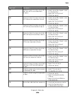
80A
T5 Timeout occurred when transmitting
image data to remote fax device.
•
Check line quality.
•
Adjust ‘Transmit Level’.
•
Select a lower ‘Max Speed’ value
under Fax Send settings.
80B
Too many errors when transmitting in ECM
mode.
•
Check line quality.
•
Adjust ‘Transmit Level’.
•
Select a lower ‘Max Speed’ value
under Fax Send settings.
80C
Remote device failed to respond to the
CTC command.
•
Select a lower ‘Max Speed’ value
under Fax Send settings.
•
Adjust ‘Transmit Level’.
80D
Received too many requests from remote
end to repeat the previous command sent.
•
Check line quality.
•
Adjust ‘Transmit Level’.
•
Check if line conditions on remote
end will facilitate a good connection.
80E
Functional limitation-Remote fax device
does not support G3 receive capability.
No action needed. Issue with the remote
device.
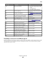
811
Failed to detect a fax device at the remote
end.
•
Verify MFD is answering to fax call
and not a voice call.
•
Decrease value of ‘Rings To Answer’
setting.
812
No more data rates available in V34
modulation scheme.
Adjust to a lower modulation scheme.
813
Timeout occurred after waiting too long to
receive a good frame.
Adjust “Receive Threshold”.
814
Tried too many times at selected speed
using V34 modulation scheme.
•
Adjust ‘Transmit Level’.
•
Adjust to a lower modulation
scheme.
815
Fax transmission was interrupted due to
power failure.
Troubleshoot MFP if error persists. See
“Modem/fax card service check” on
page 248
.
818
Fax transmission failed due to insufficient
memory to store scanned image.
Adjust ‘Memory Use’ setting to allocate
more memory for send jobs.
819
Fax transmission failed due to insufficient
memory to store received image.
Adjust ‘Memory Use’ setting to allocate
more memory for receive jobs.
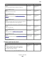
81A
A timeout occurred during transmission of
a page in ECM mode.
Select a lower ‘Max Speed’ value under
Fax Send settings.
880
Failure to transmit training successfully in
V17, V29, V27 terminal modulation
schemes.
•
Select a lower “Max Speed” under
Fax Send settings.
•
Adjust the “Transmit Level”.
•
Check line quality.
7528
Diagnostic information
255
Summary of Contents for XC4150
Page 34: ...7528 34 ...
Page 276: ...7528 276 ...
Page 294: ...Scan SE Scanner Info 7528 Service menus 294 ...
Page 317: ...3 Remove the screw B from the lower left side of the cover B 7528 Repair information 317 ...
Page 320: ...3 Remove the three screws A 7528 Repair information 320 ...
Page 327: ...3 Remove the E clip B 4 Remove the E clip C 7528 Repair information 327 ...
Page 358: ...5 Remove the two screws D from under the gear box 7528 Repair information 358 ...
Page 360: ...3 Disconnect the cable A from the LVPS 7528 Repair information 360 ...
Page 370: ...3 Disconnect the motor cable A A 7528 Repair information 370 ...
Page 371: ...4 Remove the four screws B and then remove the motor B 7528 Repair information 371 ...
Page 374: ...4 Disconnect the cable B 5 Remove the screw C securing the HVPS C 7528 Repair information 374 ...
Page 400: ...14 Remove the clip M and then remove the spacer 7528 Repair information 400 ...
Page 403: ...7528 Repair information 403 ...
Page 414: ...5 Remove the screw C from the printhead 7528 Repair information 414 ...
Page 429: ...8 Route the ADF cable through the flatbed 9 Remove the ADF 7528 Repair information 429 ...
Page 437: ...7 Disconnect the two cables B on the controller board 7528 Repair information 437 ...
Page 443: ...5 Remove the screw D and then remove the scanner tilt D 7528 Repair information 443 ...
Page 478: ...7528 478 ...
Page 485: ...7528 485 ...
Page 487: ...Assembly 1 Covers 1 2 4 6 7 8 9 1 14 10 3 5 13 13 11 11 12 7528 Parts catalog 487 ...
Page 489: ...Assembly 2 Covers 2 14 7528 Parts catalog 489 ...
Page 491: ...Assembly 3 Control panel 5 4 3 2 1 7528 Parts catalog 491 ...
Page 493: ...Assembly 4 ADF and flatbed 1 3 11 10 4 9 5 6 7 8 2 7528 Parts catalog 493 ...
Page 495: ...Assembly 5 Fuser 1 7528 Parts catalog 495 ...
Page 497: ...Assembly 6 Transfer module 1 2 7528 Parts catalog 497 ...
Page 499: ...Assembly 7 Paper feed 8 2 1 2 4 7 3 5 5 6 7528 Parts catalog 499 ...
Page 501: ...Assembly 8 Paper path 1 8 6 2 3 1 10 5 7 9 4 7528 Parts catalog 501 ...
Page 503: ...Assembly 9 Paper path 2 1 4 2 5 10 3 6 9 7 8 7528 Parts catalog 503 ...
Page 505: ...Assembly 10 Duplex 9 8 3 3 7 6 1 1 2 4 5 7528 Parts catalog 505 ...
Page 507: ...Assembly 11 Electrical 16 2 3 4 5 7 8 9 11 12 13 15 6 1 14 10 7528 Parts catalog 507 ...
Page 510: ...7528 Parts catalog 510 ...
Page 511: ...Assembly 12 550 sheet tray option 1 2 1 7528 Parts catalog 511 ...
Page 513: ...Assembly 13 550 sheet tray option 2 1 2 3 4 12 11 6 13 5 9 10 7 8 7528 Parts catalog 513 ...
Page 515: ...Assembly 14 Adjustable stand 2 2 3 3 1 7528 Parts catalog 515 ...
Page 518: ...7528 Parts catalog 518 ...
Page 520: ...7528 520 ...
Page 527: ...3 Apply the changes 7528 Appendix B Options and features 527 ...
Page 528: ...7528 528 ...
Page 554: ...7528 554 ...
Page 568: ...7528 Part number index 568 ...
Page 574: ...7528 Part name index 574 ...

