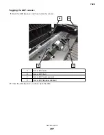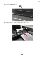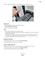
To erase the hard disk memory:
1
From the home screen, touch
Settings
>
Device
>
Maintenance
>
Out of Service Erase
.
2
Select the
Sanitize all information on hard disk
check box, and then touch
ERASE
.
3
Follow the instructions on the display.
Notes:
•
This process can take from several minutes to more than an hour, making the printer unavailable for
other tasks.
•
After removing the hard disk, return it to the next level of support.
Handling ESD
‑
sensitive parts
To prevent damage to the electrostatic discharge (ESD)-sensitive parts in the printer, do the following:
•
Turn off the printer before removing logic boards.
•
Keep the parts in their original packing material until you are ready to install them into the printer.
•
Make the least-possible movements with your body to prevent an increase of static electricity from clothing
fibers, carpets, and furniture.
•
Use the ESD wrist strap. Connect the wrist band to the system ground point. This action discharges any
static electricity in your body to the printer.
•
Hold the parts by their edge connector shroud. Do not touch its pins. If you are removing a pluggable module,
then use the correct tool.
•
If possible, keep all parts in a grounded metal cabinet.
•
Do not place the parts on the printer cover or on a metal table. If you need to put down the parts, then put
them in their packing material.
•
Prevent parts from being accidentally touched by other personnel. Cover the printer when you are not
working on it.
•
Be careful while working with the parts when cold-weather heating is used. Low humidity increases static
electricity.
Controller board/control panel replacement
Note:
Perform this procedure only if both the controller board and the control panel fail.
CAUTION—POTENTIAL INJURY:
The lithium battery in this product is not intended to be replaced.
There is a danger of explosion if a lithium battery is incorrectly replaced. Do not recharge, disassemble,
or incinerate a lithium battery. Discard used lithium batteries according to the manufacturer's instructions
and local regulations.
Warning—Potential Damage:
When replacing both the controller board and control panel, replace the parts
in the following order to avoid damaging the printer.
1
Replace the controller board first, and then start the printer into diagnostics mode.
Note:
Do not replace the control panel and controller board at the same time.
2
Turn off the printer, replace the control panel, and then start the printer into diagnostics mode.
Allow the printer to go through a complete startup cycle.
3
If the problem persists, then leave the new control panel and reinstall the old controller board.
7528
Repair information
296
Summary of Contents for XC4150
Page 34: ...7528 34 ...
Page 276: ...7528 276 ...
Page 294: ...Scan SE Scanner Info 7528 Service menus 294 ...
Page 317: ...3 Remove the screw B from the lower left side of the cover B 7528 Repair information 317 ...
Page 320: ...3 Remove the three screws A 7528 Repair information 320 ...
Page 327: ...3 Remove the E clip B 4 Remove the E clip C 7528 Repair information 327 ...
Page 358: ...5 Remove the two screws D from under the gear box 7528 Repair information 358 ...
Page 360: ...3 Disconnect the cable A from the LVPS 7528 Repair information 360 ...
Page 370: ...3 Disconnect the motor cable A A 7528 Repair information 370 ...
Page 371: ...4 Remove the four screws B and then remove the motor B 7528 Repair information 371 ...
Page 374: ...4 Disconnect the cable B 5 Remove the screw C securing the HVPS C 7528 Repair information 374 ...
Page 400: ...14 Remove the clip M and then remove the spacer 7528 Repair information 400 ...
Page 403: ...7528 Repair information 403 ...
Page 414: ...5 Remove the screw C from the printhead 7528 Repair information 414 ...
Page 429: ...8 Route the ADF cable through the flatbed 9 Remove the ADF 7528 Repair information 429 ...
Page 437: ...7 Disconnect the two cables B on the controller board 7528 Repair information 437 ...
Page 443: ...5 Remove the screw D and then remove the scanner tilt D 7528 Repair information 443 ...
Page 478: ...7528 478 ...
Page 485: ...7528 485 ...
Page 487: ...Assembly 1 Covers 1 2 4 6 7 8 9 1 14 10 3 5 13 13 11 11 12 7528 Parts catalog 487 ...
Page 489: ...Assembly 2 Covers 2 14 7528 Parts catalog 489 ...
Page 491: ...Assembly 3 Control panel 5 4 3 2 1 7528 Parts catalog 491 ...
Page 493: ...Assembly 4 ADF and flatbed 1 3 11 10 4 9 5 6 7 8 2 7528 Parts catalog 493 ...
Page 495: ...Assembly 5 Fuser 1 7528 Parts catalog 495 ...
Page 497: ...Assembly 6 Transfer module 1 2 7528 Parts catalog 497 ...
Page 499: ...Assembly 7 Paper feed 8 2 1 2 4 7 3 5 5 6 7528 Parts catalog 499 ...
Page 501: ...Assembly 8 Paper path 1 8 6 2 3 1 10 5 7 9 4 7528 Parts catalog 501 ...
Page 503: ...Assembly 9 Paper path 2 1 4 2 5 10 3 6 9 7 8 7528 Parts catalog 503 ...
Page 505: ...Assembly 10 Duplex 9 8 3 3 7 6 1 1 2 4 5 7528 Parts catalog 505 ...
Page 507: ...Assembly 11 Electrical 16 2 3 4 5 7 8 9 11 12 13 15 6 1 14 10 7528 Parts catalog 507 ...
Page 510: ...7528 Parts catalog 510 ...
Page 511: ...Assembly 12 550 sheet tray option 1 2 1 7528 Parts catalog 511 ...
Page 513: ...Assembly 13 550 sheet tray option 2 1 2 3 4 12 11 6 13 5 9 10 7 8 7528 Parts catalog 513 ...
Page 515: ...Assembly 14 Adjustable stand 2 2 3 3 1 7528 Parts catalog 515 ...
Page 518: ...7528 Parts catalog 518 ...
Page 520: ...7528 520 ...
Page 527: ...3 Apply the changes 7528 Appendix B Options and features 527 ...
Page 528: ...7528 528 ...
Page 554: ...7528 554 ...
Page 568: ...7528 Part number index 568 ...
Page 574: ...7528 Part name index 574 ...

