Scheduled maintenance
The control panel displays an
80.xx
error when it reaches certain page counts. It is necessary to replace the
appropriate maintenance kit to maintain print quality and printer reliability. Reset the maintenance counter after
replacing the maintenance kit.
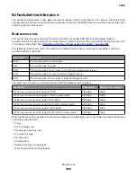
Maintenance kits
The printer may stop printing when the fuser rated life is reached. After 150K printed pages (sides) a
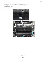
maintenance kit may be required. The correct fuser maintenance kit must be installed for the type of fuser that
is installed in the printer. See
“Identifying the type of fuser used in the printer” on page 481
.
The following table shows the error codes that indicate that the fuser is nearing its end of life, and that a
maintenance kit is required:
Error code
Description
80.0x
The maintenance kit is nearly low.
80.1x
The maintenance kit is low.
80.2x
The maintenance kit is very low. Only 2000 estimated pages remain.
80.3x
The maintenance kit is low. 0 estimated pages remain.
80.4x
The maintenance kit is very low. 0 estimated pages remain.
The parts are available as a maintenance kit with the following part numbers:
Description
Part number
Maintenance interval
CS72x fuser maintenance kit, type 02, 100V
41X0552
150K
CS72x fuser maintenance kit, type 07, 100V, narrow media
41X0553
150K
CS72x fuser maintenance kit, type 00, 110–120V
41X0554
150K
CS72x fuser maintenance kit, type 05, 110–120V, narrow media
41X0555
150K
CS72x fuser maintenance kit, type 01, 220–240V
41X0556
150K
CS72x fuser maintenance kit, type 06, 220–240V, narrow media
41X0557
150K
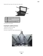
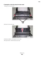
When performing the scheduled maintenance procedure, the following areas should be cleaned of media dust
and toner contamination:
•
Trays
•
PC cartridge area
•
Developer housings area
•
Transfer roll area
•
Duplex area
•
Standard bin
•
Bridge unit area (if equipped)
•
Finisher media bins (if equipped)
7528
Maintenance
480
Summary of Contents for XC4150
Page 34: ...7528 34 ...
Page 276: ...7528 276 ...
Page 294: ...Scan SE Scanner Info 7528 Service menus 294 ...
Page 317: ...3 Remove the screw B from the lower left side of the cover B 7528 Repair information 317 ...
Page 320: ...3 Remove the three screws A 7528 Repair information 320 ...
Page 327: ...3 Remove the E clip B 4 Remove the E clip C 7528 Repair information 327 ...
Page 358: ...5 Remove the two screws D from under the gear box 7528 Repair information 358 ...
Page 360: ...3 Disconnect the cable A from the LVPS 7528 Repair information 360 ...
Page 370: ...3 Disconnect the motor cable A A 7528 Repair information 370 ...
Page 371: ...4 Remove the four screws B and then remove the motor B 7528 Repair information 371 ...
Page 374: ...4 Disconnect the cable B 5 Remove the screw C securing the HVPS C 7528 Repair information 374 ...
Page 400: ...14 Remove the clip M and then remove the spacer 7528 Repair information 400 ...
Page 403: ...7528 Repair information 403 ...
Page 414: ...5 Remove the screw C from the printhead 7528 Repair information 414 ...
Page 429: ...8 Route the ADF cable through the flatbed 9 Remove the ADF 7528 Repair information 429 ...
Page 437: ...7 Disconnect the two cables B on the controller board 7528 Repair information 437 ...
Page 443: ...5 Remove the screw D and then remove the scanner tilt D 7528 Repair information 443 ...
Page 478: ...7528 478 ...
Page 485: ...7528 485 ...
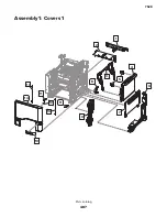
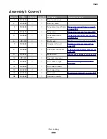
Page 487: ...Assembly 1 Covers 1 2 4 6 7 8 9 1 14 10 3 5 13 13 11 11 12 7528 Parts catalog 487 ...
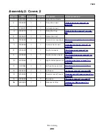
Page 489: ...Assembly 2 Covers 2 14 7528 Parts catalog 489 ...
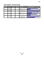
Page 491: ...Assembly 3 Control panel 5 4 3 2 1 7528 Parts catalog 491 ...
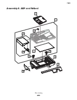
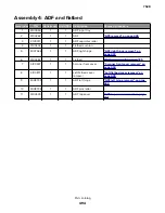
Page 493: ...Assembly 4 ADF and flatbed 1 3 11 10 4 9 5 6 7 8 2 7528 Parts catalog 493 ...
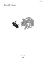
Page 495: ...Assembly 5 Fuser 1 7528 Parts catalog 495 ...
Page 497: ...Assembly 6 Transfer module 1 2 7528 Parts catalog 497 ...
Page 499: ...Assembly 7 Paper feed 8 2 1 2 4 7 3 5 5 6 7528 Parts catalog 499 ...
Page 501: ...Assembly 8 Paper path 1 8 6 2 3 1 10 5 7 9 4 7528 Parts catalog 501 ...
Page 503: ...Assembly 9 Paper path 2 1 4 2 5 10 3 6 9 7 8 7528 Parts catalog 503 ...
Page 505: ...Assembly 10 Duplex 9 8 3 3 7 6 1 1 2 4 5 7528 Parts catalog 505 ...
Page 507: ...Assembly 11 Electrical 16 2 3 4 5 7 8 9 11 12 13 15 6 1 14 10 7528 Parts catalog 507 ...
Page 510: ...7528 Parts catalog 510 ...
Page 511: ...Assembly 12 550 sheet tray option 1 2 1 7528 Parts catalog 511 ...
Page 513: ...Assembly 13 550 sheet tray option 2 1 2 3 4 12 11 6 13 5 9 10 7 8 7528 Parts catalog 513 ...
Page 515: ...Assembly 14 Adjustable stand 2 2 3 3 1 7528 Parts catalog 515 ...
Page 518: ...7528 Parts catalog 518 ...
Page 520: ...7528 520 ...
Page 527: ...3 Apply the changes 7528 Appendix B Options and features 527 ...
Page 528: ...7528 528 ...
Page 554: ...7528 554 ...
Page 568: ...7528 Part number index 568 ...
Page 574: ...7528 Part name index 574 ...

