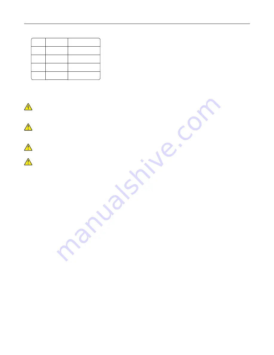
1
Top
330 mm (13 in.)
2
Rear
203 mm (8 in.)
3
Right side 152 mm (6 in.)
4
Front
381 mm (15 in.)
5
Left side
457 mm (18 in.)
Attaching cables
CAUTION—SHOCK HAZARD:
To avoid the risk of electrical shock, do not set up this product or make
any electrical or cabling connections, such as the power cord, fax feature, or telephone, during a
lightning storm.
CAUTION—POTENTIAL INJURY:
To avoid the risk of fire or electrical shock, connect the power cord to
an appropriately rated and properly grounded electrical outlet that is near the product and easily
accessible.
CAUTION—POTENTIAL INJURY:
To avoid the risk of fire or electrical shock, use only the power cord
provided with this product or the manufacturer's authorized replacement.
CAUTION—POTENTIAL INJURY:
To reduce the risk of fire, use only a 26 AWG or larger
telecommunications (RJ-11) cord when connecting this product to the public switched telephone
network. For users in Australia, the cord must be approved by the Australian Communications and Media
Authority.
Warning—Potential Damage:
To avoid loss of data or printer malfunction, do not touch the USB cable, any
wireless network adapter, or the printer in the areas shown while actively printing.
Set up, install, and configure
36
Summary of Contents for XC9445
Page 6: ...Notices 483 Index 497 Contents 6 ...
Page 84: ...8 Remove tray 2 9 Secure the spacer to the printer with screws Set up install and configure 84 ...
Page 103: ...6 Install the optional tray Set up install and configure 103 ...
Page 104: ...7 Connect the tray connector to the printer Set up install and configure 104 ...
Page 106: ...Installing the banner tray 1 Turn off the printer Set up install and configure 106 ...
Page 111: ...Installing the working shelf 1 Turn off the printer Set up install and configure 111 ...
Page 113: ...6 Secure the shelf to the printer 7 Turn on the printer Set up install and configure 113 ...
Page 120: ...Set up install and configure 120 ...
Page 127: ...12 Attach the finisher to the printer Set up install and configure 127 ...
Page 135: ...8 Close the booklet finisher door 9 Insert the bins Set up install and configure 135 ...
Page 136: ...10 Insert the booklet finisher cable Set up install and configure 136 ...
Page 140: ...17 Remove the rear ports cover 18 Secure the cable Set up install and configure 140 ...
Page 148: ...3 Unplug the booklet finisher cables from the printer Set up install and configure 148 ...
Page 164: ...6 Attach the hard disk to the controller board Set up install and configure 164 ...
Page 166: ...8 Attach the controller board access cover Set up install and configure 166 ...
Page 170: ...Set up install and configure 170 ...
Page 174: ...9 Secure the ISP to the printer Set up install and configure 174 ...
Page 175: ...10 Attach the controller board access cover Set up install and configure 175 ...
Page 299: ...Replacing a photoconductor unit 1 Open the front door Maintain the printer 299 ...
Page 307: ...3 Insert the new tray insert Maintain the printer 307 ...
Page 309: ...Maintain the printer 309 ...
Page 310: ...3 Unlock the fuser Maintain the printer 310 ...
Page 311: ...4 Remove the used fuser 5 Unpack the new fuser Maintain the printer 311 ...
Page 313: ...2 Remove the used printhead wiper 3 Unpack the new printhead wiper Maintain the printer 313 ...
Page 314: ...4 Insert the new printhead wiper 5 Close the front door Maintain the printer 314 ...
Page 315: ...Replacing the transfer module cleaner 1 Open the front door Maintain the printer 315 ...
Page 318: ...5 Insert the new transfer module cleaner Maintain the printer 318 ...
Page 320: ...Replacing the tray roller kit 1 Turn off the printer Maintain the printer 320 ...
Page 322: ...4 Unpack the new tray roller kit Maintain the printer 322 ...
Page 324: ...Replacing the ADF roller kit 1 Turn off the printer Maintain the printer 324 ...
Page 325: ...2 Open the ADF top cover 3 Remove the separator roller cover Maintain the printer 325 ...
Page 327: ...8 Open the ADF inner cover 9 Remove the roller clip Maintain the printer 327 ...
Page 329: ...13 Attach the roller clip until it clicks into place Maintain the printer 329 ...
Page 331: ...Replacing the 2000 sheet tray roller kit 1 Turn off the printer Maintain the printer 331 ...
Page 333: ...4 Locate and remove the used roller kit 5 Unpack the new roller kit Maintain the printer 333 ...
Page 340: ...6 Unpack the new tray roller kit Maintain the printer 340 ...
Page 343: ...3 Remove the used second transfer roller Maintain the printer 343 ...
Page 346: ...Replacing the waste toner bottle 1 Open the front door Maintain the printer 346 ...
Page 354: ...4 Insert the new small cover 5 Insert the tray Maintain the printer 354 ...
Page 361: ...Replacing the trifold Z fold finisher bin 1 Turn off the printer Maintain the printer 361 ...
Page 364: ...4 Insert the new paper bail until it clicks into place Maintain the printer 364 ...
Page 368: ...4 Attach the new controller board access cover Maintain the printer 368 ...
Page 384: ... Scanner glass pad ADF glass Scanner glass 3 Close the scanner cover Maintain the printer 384 ...
Page 385: ...Cleaning the tray roller kit 1 Turn off the printer Maintain the printer 385 ...
Page 389: ...Cleaning the 2000 sheet tray roller kit 1 Turn off the printer Maintain the printer 389 ...
Page 431: ...Troubleshoot a problem 431 ...
Page 455: ...5 Close the cover 6 Open the booklet finisher door Troubleshoot a problem 455 ...


