
Remote Monitoring System Settings
76
Planar UltraRes Series User Manual
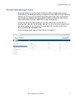
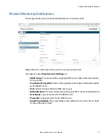
The options under
Notification Events
are:
•
Power On/Off:
Occurs when standby mode is entered and when the display is
powered on.
•
System Error:
Occurs when the display has detected an error within the
system.
•
Source Detect:
Occurs when the display detects and displays a new input
signal.
•
Source Lost:
Occurs when the current input signal is no longer detected.
•
Source Selected:
Occurs when a different input source is selected for any of the
zones.
Note:
Each event can be sent to one or more recipients. To add multiple email addresses,
separate them by a space.
•
Test Email:
Sends a test of the selected email notification. This is useful for
verifying that your email account settings are setup correctly. If the test email
fails, you can use the
View Last 10 Log Messages
button to get more detailed
information about the failure.
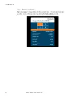
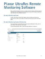
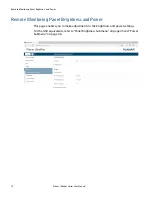
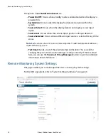
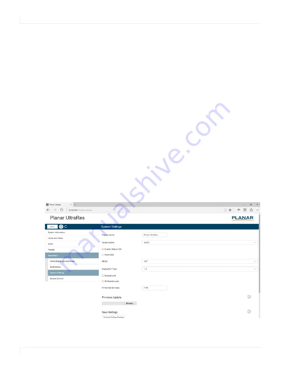
Remote Monitoring System Settings
This page enables you to make adjustments to a variety of system settings.
For the OSD equivalent, refer to "System Settings Submenu" on page 63.
Summary of Contents for Planar UltraRes Series
Page 1: ...Planar UltraRes Series User Manual UR7551 MX UR8651 MX UR9851 ...
Page 6: ...Table of Contents iv Planar UltraRes Series User Manual ...
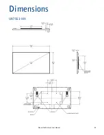
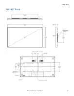
Page 92: ...Planar UltraRes Series User Manual 86 Dimensions UR7551 MX ...
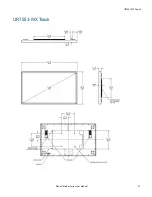
Page 93: ...UR7551 MX Touch Planar UltraRes Series User Manual 87 UR7551 MX Touch ...
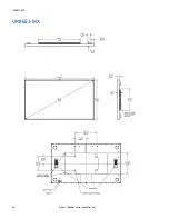
Page 94: ...UR8651 MX 88 Planar UltraRes Series User Manual UR8651 MX ...
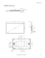
Page 95: ...UR8651 MX Touch Planar UltraRes Series User Manual 89 UR8651 MX Touch ...
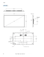
Page 96: ...UR9851 90 Planar UltraRes Series User Manual UR9851 ...
Page 97: ...UR9851 Touch Planar UltraRes Series User Manual 91 UR9851 Touch ...


