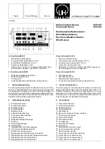
K
Eingangsbuchse für Temperaturfühler 2
L
Eingangsbuchse für Temperaturfühler 1
M
Hauptschalter (auf der Rückseite)
N
Netzspannungsversorgung mit Sicherung (auf der Rückseite)
O
PROG. - Taste (auf der Rückseite)
P
KALIB. - Taste (auf der Rückseite)
3
Funktionsweise
Die Meßwerte werden nacheinander vom Mikroprozessor gele-
sen, linearisiert und angezeigt. Weiterhin werden ständig die
MIN- und MAX-Werte gespeichert und können über die Taste
5
angezeigt werden.
Über die RS 232-Schnittstelle (seriell) werden die Meßwerte
ständig und über die Centronics-Schnittstelle in einstellbaren
Intervallen ausgegeben.
4
Inbetriebnahme
Meßfühler und Wind-Meßaufnehmer an die Buchsen
G
-
L
an-
schließen. Netzkabel mit Netzeingang
M
verbinden und Gerät
mit Schalter
N
einschalten.
Achtung:
Bei Außenmessungen sind die Temperatur-, Feuchte- und
Sonnenscheindauer-Fühler gegen Regen zu schützen.
5
Funktionsbeschreibung
5.1
Temperaturmessung
Die Temperaturfühler werden gemäß Kennzeichnung an die
Buchsen
K
und
L
angeschlossen. Bei Außentemperaturmes-
sung ist der Fühler gegen direkte Sonneneinstrahlung und ge-
gen Regen zu schützen. Die Messung erfolgt an der Fühlerspit-
ze; die Meßdaten werden auf den Displays
1
und
2
ange-
zeigt.
5.2
Feuchtemessung
Die Feuchtefühler werden gemäß Kennzeichnung an Buchse
I
und
J
angeschlossen. Um genaue Messungen zu erzielen,
muß der Feuchtraumfühler in der Nähe des Temperaturfühlers
moniert werden. Bei der Umrechnung in % rel. Luftfeuchte wird
automatisch die Temperatur berücksichtigt. Bei Außenmontage
ist der Fühler gegen direkte Sonneneinstrahlung und gegen
Regen zu schützen. Die Anzeige erfolgt auf den Displays
3
und
4
.
5.3
Messung der Sonnenscheindauer
Der Fühler wird an Buchse
H
angeschlossen und ist in Rich-
tung der Mittagssonne zu montieren.
Die Sonnenscheindauer wird mit einer Auflösung von 0,1 Std.
bis zu einer Gesamtdauer von 10 Std. angezeigt.
Ab 10 Std. erfolgt eine automatische Umschaltung zu einer Auf-
lösung von 1 Std.
Das Ergebnis der Sonnenscheindauermessung wird jeweils
abends gespeichert und am nächsten Morgen gelöscht, so daß
die Zählung bei Null beginnt. Durch Betätigen des Tasters
5
erscheint das Ergebnis des Vortages.
5.4
Messung der Windgeschwindigkeit und -richtung
Der Windmeßaufnehmer 666 349 wird an Buchse (
G
ange-
schlossen und ist an einer freien Stelle z. B. einige Meter ober-
halb des Hausdaches an einem Antennenmast zu montieren.
Der Mast muß geerdet werden (VDE-Vorschriften einhalten)
und die Statik ist zu beachten. Die Arbeiten sollten nur von ei-
nem Fachmann durchgeführt werden.
Der Windrichtungsanzeiger muß einmalig ausgerichtet werden.
Die Spitze muß hierbei nach Norden ausgerichtet bleiben; das
Vierkant-Trägerrohr wird solange am Mast gedreht, bis auf dem
Display
B
0 Grad erscheint. Dazu wird der Windrichtungsan-
zeiger bei eingeschalteter Wetterstation einmal um 360° ge-
K
Input socket for temperature sensor 2
L
Input socket for temperature sensor 1
M
Main switch (on rear of device)
N
Mains power supply with fuse (on rear of device)
O
PROG. key (on rear of device)
P
CALIB. key (on rear of device)
3
Function
The microprocessor reads, linearizes and displays the measu-
red values one after another. In addition, the MIN and MAX va-
lues are continually saved and can be displayed using key
5
.
The measured values are output continuously via the RS 232
(serial) interface and at an adjustable interval via the Centro-
nics (parallel) interface.
4
Putting into operation
Connect the measuring sensors and wind sensor to sockets
G
through
L
. Connect the power lead to mains input
M
and
switch on the device with switch
N
.
Attention:
Protect the temperature, humidity and sunshine period sensors
from rain when measuring out of doors!
5
Description of function
5.1
Temperature measurement
The temperature sensors are connected to sockets
K
and
L
according to the respective designations. When measuring the
outdoor temperature, the sensor must be protected from direct
sunshine and rain. The measuring point is the tip of the sensor;
measurement data appear on the displays
1
and
2
.
5.2
Humidity measurement
The humidity sensors are connected to sockets
I
and
J
according to the respective designations. In order to obtain
accurate measurements, the humidity sensor must be mounted
near the temperature sensor. The temperature is automatically
taken into consideration in converting to percent relative
humidity. When measuring out of doors, the sensor must
be protected from direct sunshine and rain. The measurement
data appear on the displays
3
and
4
.
5.3
Measuring the sunshine period
The sensor is connected to socket
H
so that it points toward the
position of the sun at midday.
The sunshine period is displayed with a resolution from 0.1
hours up to a total period of 10 hours.
Above 10 hours, the device automatically switches to a re-
solution of 1 hour.
The result of the sunshine period measurement is stored every
evening and reset the next morning, so that the count begins
again at zero. Pressing the key
5
displays the result of the
previous day.
5.4
Measuring wind speed and direction
The wind sensor 666 349 is connected to socket (
G
and should
be mounted at a free site e.g. several meters above the rooftop
on an antenna mast.
The mast must be grounded (observe VDE regulations or your
equivalent local regulations); make sure that the mast and roof-
top can bear the additional load. Installation should only be
carried out by a trained service person.
The wind direction sensor must be adjusted only once. Its tip
must point toward true (geographic) north: the square
supporting rod is turned on the mast until the display
B
reads 0
degrees. Next, while the weather station is switched on, the
2


