dreht und danach die Spitze nach Norden ausgerichtet. Danach
ist die Windmeßeinrichtung betriebsbereit.
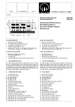
Die Windrichtung wird auf dem Display
B
mit einer Auflösung
von 10 Grad und auf der Windrose
A
mit einer Auflösung von
22,5 Grad angezeigt. Auf Display
9
wird die Windgeschwindig-
keit in m/sec angezeigt. Die Windrichtungs- und Windge-
schwindigkeitsaufnehmer besitzen eine elektrische Heizung,
so daß sich kein Kondenswasser bilden kann und ein Betrieb
bis -40°C möglich ist.
5.5
Luftdruckmessung
Der Luftdruck wird auf dem Display
8
in hPa angezeigt. Es
wird der tatsächliche Luftdruck am Aufstellungsort gemessen.
Liegt der Aufstellungsort oberhalb der Meereshöhe, so kann
eine Höhenkorrektur bis 2000 m erfolgen (s. Abgleich und Pro-
grammierung).
Über vier Leuchtdioden
6
erfolgt eine Luftdrucktendenzanzei-
ge. Hierbei wird zwischen "langsam" (eine LED an) oder
"schnell" (zwei LEDs an) steigendem oder fallendem Luftdruck
unterschieden. Bei konstantem Luftdruck sind die LEDs erlo-
schen.
5.6
RS 232-Schnittstelle
Die Wetterstation kann mit dem Anschlußkabel 667 931 (an
beiden Enden eine 25-polige Buchse, Pins 2-3, 4-5, 6-20 sind
gekreuzt) an die serielle Schnittstelle eines Computers (Be-
triebssystem: MS-DOS ab Version 3.20) angeschlossen wer-
den. Mit der beiliegenden Software können die Meßwerte er-
faßt und grafisch dargestellt werden.
5.7
Centronics-Schnittstelle
An die Buchsenleiste
E
kann mit Hilfe des Kabels 728 069 ein
Drucker angeschlossen werden. Die Meßwerte können in ein-
stellbaren Intervallen (mit Schiebeschalter
D
) ausgedruckt
werden.
5.8
MIN-MAX-Werte
Durch einmaliges Betätigen des Tasters
5
werden die Mini-
malwerte und durch ein weiteres Betätigen des Tasters die Ma-
ximalwerte des vorangegangenen Tages angezeigt. Zusätzlich
leuchten die unteren bzw. oberen LEDs
6
der Tendenzanzei-
ge. Nach der letzten Tastenbetätigung geht die Wetterstation in
den aktuellen Meß- und Anzeigemodus zurück.
6
Abgleich und Programmierung
Die Meßwertaufnehmer (Temperatur, Feuchte, Sonnenschein-
dauer) müssen bei Sensortausch bzw. bei Ersatzteilbeschaf-
fung neu kalibriert werden. Hierzu stehen zwei verschiedene
Abgleichmöglichkeiten zur Verfügung.
1. Zahlencode-Abgleich
Alle Sensoren sind werkseitig ausgemessen; deshalb liegen je-
dem Temperatur-, Feuchte- und Sonnenscheindauerfühler je-
weils zwei vierstellige Zahlencodes bei, die die exakten Ab-
gleichdaten repräsentieren. Zur Eingabe der Zahlencodes wer-
den die rückseitigen Tasten PROG
O
und KALIB
P
für minde-
stens 3 Sekunden gleichzeitig gedrückt - die Wetterstation wird
dadurch in den Kalibriermodus geschaltet; im Display "Windge-
schwindigkeit"
9
wird dies durch
C1 (C2 = Individualabgleich)
angezeigt. Eine kurze Betätigung der rückseitigen Taste KALIB
P
schaltet zwischen
C1 (Zahlencodeabgleich) und C2 (Indivi-
dualabgleich) um.
wind direction sensor is turned through 360 ° and then the tip is
once again aligned with true north. The wind sensor is now
ready for operation.
The wind direction is shown on the display
B
with a resolution
of 10 degrees and on the compass rose
A
with a resolution of
22.5 degrees. The display
9
shows the wind speed in m/sec.
The wind direction and wind speed sensors are equipped with
electric heating, so that no water condensation can occur and
the system can operate reliably at temperatures as low as -40°C.
5.5
Air pressure measurement
The air pressure is shown on the display
8
in hPa. The system
measures the actual air pressure at the measuring site. If the
measuring site is above sea level, the you can correct for an
altitude of up to 2000 m (see section "Calibrating and configu-
ring the weather station").
The tendency of the air pressure is indicated by four LEDs
6
.
The indicator distinguishes between "slow" (one LED on) or
"fast" (two LEDs on) increases or decreases in air pressure. At
a constant air pressure all LEDs are extinguished.
5.6
RS 232 interface
The weather station can be connected to the serial interface of
an MS-DOS computer (DOS version 3.20 or higher) by means
of the connection cable for computers 667 931 (25-pin sub-D
socket at each end, pins 2-3, 4-5, 6-20 crossed). The software
included in the scope of supply enables you to record and
graphically display the measured values.
5.7
Centronics interface
Using the PC printer cable 728 069, you can connect the device
to a printer via the connector
E
. You can print out the measured
values at adjustable intervals (set via slide switch
D
).
5.8
MIN-MAX values
Pressing the key
5
once displays the previous day’s minimum
values; pressing it twice displays the corresponding maximum
values. In addition, the top or bottom LEDs
6
of the tendency
indicator light up. After the last key press, the weather station
returns to the current measuring and display mode.
6
Calibrating and configuring the weather station
The measurement sensors (temperature, humidity, sunshine
period) must be recalibrated every time sensors are exchanged
or old sensors replaced. You can use one of two calibration
methods.
1. Numeric code calibration
All sensors are factory tested; thus, every temperature, humidity
and sunshine period sensor is supplied with two four-digit
numeric codes, which represent the exact calibration data. To
enter the numeric codes, hold down the PROG
O
and CALIB
P
keys (located on the rear of the device) at the same time for at
least three seconds. This activates the weather station’s cali-
bration mode. The display "Wind speed"
9
indicates this by
showing the message
C1 (C2 = individual calibration). Pressing
the key CALIB
P
on the rear of the device toggles between
C1
(numeric code calibration) and
C2 (individual calibration).
3


