2
3 Technische Beschreibung
Die Antennen wurden für eine Frequenz f = 9,40 GHz, das ent-
spricht einer Freiraumwellenlänge
l
0
ª
32 mm, unter Berücksich-
tigung von Verkürzungsfaktoren entwickelt. Alle Messing- teile
sind zum Schutz gegen Korrosion vernickelt. Die im Antennen-
stab eingebaute Schottky Barrier Detektordiode benötigt zum
Betrieb einen kleinen D.C. Vorstrom, der vom Antennendreh-
tisch (737 400) erzeugt wird. Der Antennenstab ist aus faser-
verstärktem Epoxydharz gefertigt.
4 Montage
Der Antennenstab trägt als Grundausstattung einen
l
/2-Dipol
mit Empfangsdiode. Verbinden Sie den Antennenstab mit dem
vorgesehenen Halter. Die so entstandene Einheit passt in die
Zentralaufnahme für Steckachsen im Antennendrehtisch. Sie ist
geeignet, um Horizontaldiagramme von Dipolantennen zu unter-
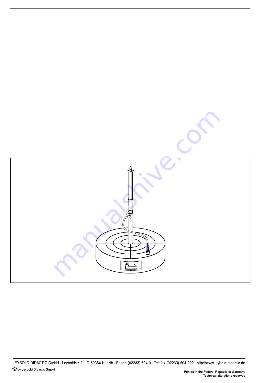
suchen. Schließen Sie den Stecker des Antennenausgangka-
bels an die BNC Buchse im Drehteller an s. Fig. 2. Auf den
l
/2-
Dipol des Antennenstabes können Sie paarweise die Verlänge-
rungen 4...8 aus Fig. 1 aufstecken. Achten Sie dabei auf den
Schutz der Grafitschicht! Die Aufnahme von Vertikaldiagrammen
geschieht mit dem entsprechenden Ausleger vgl. Fig.1.
3 Technical Description
The antennas were designed for a frequency of f = 9.40 GHz,
which corresponds to a free-space wavelength
l
0
ª
32 mm.
The construction was carried out taking the effective electrical
lengths of the wires into consideration. All of the brass parts
are nickel-plated to protect against corrosion. A small DC bias
current is required to operate the Schottky-barrier detector di-
ode. This current is generated by the rotating antenna plat-
form (737 400). The antenna rod is manufactured out of fibre-
reinforced epoxy resin.
4 Assembly
The basic version of the antenna rod forms a
l
/2 dipole with
receiving diode. Connect the antenna rod with the holder pro-
vided. This unit fits into the central mount for attaching stand
rods onto the rotating antenna platform. It is now suitable for
the investigation of horizontal diagrams of dipole antennas.
Connect the plug of the antenna output cable to the BNC
socket on the rotating base, see Fig. 2. The extensions 4...8
from Fig. 1 can be attached in pairs onto the
l
/2 dipole of the
antenna rod. Please take care not to damage the graphite
coating! The recording of the vertical diagrams is carried out
with the appropriate arm, cf. Fig. 1.
Fig. 2: Zusammenbau einer 2
l
-Dipolantenne und Einsetzen in den An-
tennendrehtisch
Fig. 2: Assembly of 2
l
dipole antenna and installation on the rotating
antenna platform.


