background image


8


6.  Now locate all the component parts, which make up the TSG mounting plate 

assembly, reference page 9 to identify them.  The centerline of the two mounting 
plates should be spaced at least 30” apart.  Hold parts up to locate holes 
required in truck chassis and mark gussets and plates for trimming. 

 
7.  Lower floor jack and let gate swing out of the way.  Drill 9/16” holes through 

chassis to attach both mounting plates.  Bolt plates in place using hardware 
supplied.  Lift trunion tube of gate back in position. 


8.  Now tack weld the gussets and support plate to the mounting plate and trunion 

tube.  Welds must be strong enough to support the gate without a load on the 
platform. 


9.  Locate a suitable spot to mount the power unit enclosure.  Use the two brackets 

and shims supplied.  Refer to the sketch on page 10.  Connect the hydraulic 
hose and plastic tubing from the lift cylinder to the power unit.  


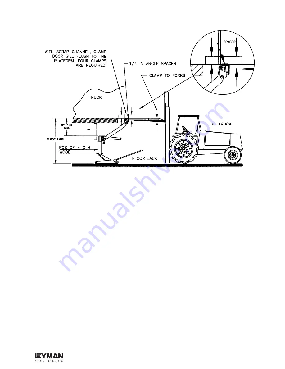
10. Unclamp the four clamps holding the back of the platform next to the door sill.  

Caution:

 Do not unclamp the tip of the platform. 


11. Let the lift truck forks down slowly until they will not go any further.  They will stop 

about half way down when they meet resistance from the oil in the lift cylinder. 


Summary of Contents for TSG Hide-A-Way

Page 1: ...nstallation Manual TSG Hide A Way Truck Side Gate 10335 Wayne Avenue Cincinnati OH 45215 Ph 513 891 6210 Toll Free 866 539 6261 Fax 513 891 4761 www leymanlift com sales leymanlift com LML00120 4 22 1...

Page 2: ...gate 4 General View Truck Mounting 5 Truck Prep before Mounting Gate 6 Mounting Gate to Truck side door 6 12 Mounting Plate Assembly Reference 9 Recommended Oils 13 TSG Wiring 14 Decal placement 15 Fi...

Page 3: ...ed and the cause of the noise should be pin pointed and corrected 10 Do not over load the maximum rated capacity is based on an evenly distributed load all over the platforms flat surface 11 Always lo...

Page 4: ...OPERATING OF THE LIFT GATE Before operating the lift read and understand this decal urgent warning decal and the Owner s Manual Do not stand behind the lift gate while unfolding or using the platform...

Page 5: ...5...

Page 6: ...erves as the up stop for the gate Step 2 MOUNTING GATE TO TRUCK SIDE DOOR 1 Unfold the secondary platform 2 Clamp the secondary platform to the lift truck approximately centered see illustration on pa...

Page 7: ...7 TSG SILL CUTOUT...

Page 8: ...position 8 Now tack weld the gussets and support plate to the mounting plate and trunion tube Welds must be strong enough to support the gate without a load on the platform 9 Locate a suitable spot to...

Page 9: ...800 613 Mounting plate 2 2 BP 800 284 Gusset 3 12 P11029 Bolt GR 8 1 2 13 x 2 1 2 4 12 P23511 Lock nut 1 2 5 24 P26004 Flat washer 1 2 6 2 S577 008 000 Support St Angle 2 1 2x2x3 8x8 7 4 AP 999 023 G...

Page 10: ...10 Index Req d Part Part Name Material Size 1 2 BP 800 288 Power unit bracket 2 2 AT 998 007 112 Shim plate 1 8 x 3 x 6 3 4 P11029 Bolt 1 2 13x2 1 2 4 4 P23511 Lock nut 1 2 5 8 P26004 Flat washer 1 2...

Page 11: ...instead of a flip ramp the fixed taper will be off the ground It should come within 1 of the ground when the platform is loaded TSG platforms are level ride 15 If the gate operation is correct finish...

Page 12: ...resting on brackets approximately 1 2 above cylinder Weld solid down both sides as shown 1 4 fillet weld Caution Ground arms before welding brackets 20 Trucks Run 4 gauge power line from 150 amp circ...

Page 13: ...ange Chevron RYKON ISO 15 15o F to 150o F Mobil DTE 11 15o F to 150o F Shell TELLUS T15 15o F to 150o F Level 2 Cold Conditions Manufacturer Type Temperature Range Chevron AVIATION A 50o F to 80o F Mo...

Page 14: ...tches located on opposite side from door hinges Switch keyways must face down Drill a 2 1 4 hole through the outside wall at desired locations to mount toggle switches Must use heat shrink tubing prov...

Page 15: ...EMENT Stand Clear Bottom of Platform P55198 2 Secure Latch P55202 Operation of Lift Gate P55307 Max Capacity Decal Urgent Warning P55199 Read and Understand P55203 Shut Off Power P55201 Extreme Shield...

Page 16: ...er grommets if you prefer Charge line power line clamped to bottom of cross members with loom clamps Electric line from gate to power pack through cross members with rubber grommets if you prefer Elec...

Page 17: ...rcuit breaker Platform will not lower 1 Battery is low 2 Bad ground or electrical connection 3 Lowering valve is bad 1 Recharge the batteries 2 Check for corrosion and tighten 3 Check the coil Platfor...

Page 18: ...________________________________________________________________ ______________________________________________________________________________ ________________________________________________________...

Reviews: