Chapter 2. SYSTEM CONFIGURATION
2 - 4
2.3 System Configuration Types
System configuration is classified into 3 types that Basic system, Computer link system executing data
communications between the CPU module and a computer by use of a computer link module(G6L-CUEB/C ) and
Network system controlling the PLC and remote I/O modules.
2.3.1 Basic System
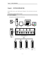
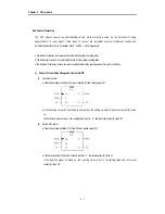
The following describes basic system.
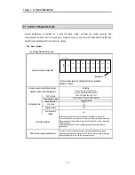
Example of System configuration
(The above figure shows the configuration where 16-input/output
modules are loaded.)
Maximum number of Input/Output modules
8 modules
Maximum number of Input/Output points
•
16-point module mounted: 128 points
•
32-point module mounted: 256 points
CPU module
GM6-CPUA, GM6-CPUB, GM6-CPUC
Power Supply module
GM6-PAFA, GM6-PAFB, GM6-PD3A, GM6-PDFA
Basic Base Unit
GM6-B04/06/08M
I/O module
G6I-
G6Q-
Special module
G6F-
Configuration units
Communication
module
G6L-
I/O number allocation
64 points are allocated to each slot in a base board whatever it is empty or not.
There's no limitation for the location and the number of special modules on base board.
Special modules do not have fixed I/O numbers while a fixed I/O number is allocated to
a digital I/O module.
A dedicated function block controls a special module and memory is allocated
automatically.
Note for power supply module selection
•
To use A/D, D/A conversion module, be sure to select GM6-PAFB power supply
module that supplies
±
15VDC instead of 24VDC.
±
15VDC power is need for operation
of internal analog circuit of A/D and D/A conversion modules.
Base Board
POWER
CPU
0.0.0
~
0.0.15
0.1.0
~
0.1.15
0.2.0
~
0.2.15
0.3.0
~
0.3.15
0.4.0
~
0.4.15
0.5.0
~
0.5.15
0.6.0
~
0.6.15
0.7.0
~
0.7.15
Slot number 0 1 2 3 4 5 6 7


