Chapter 15. The PID functions
15-12
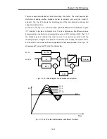
There are several methods to avoid the windup of actuator. The most popular two
methods are adding another feedback system to actuator, and using the model of
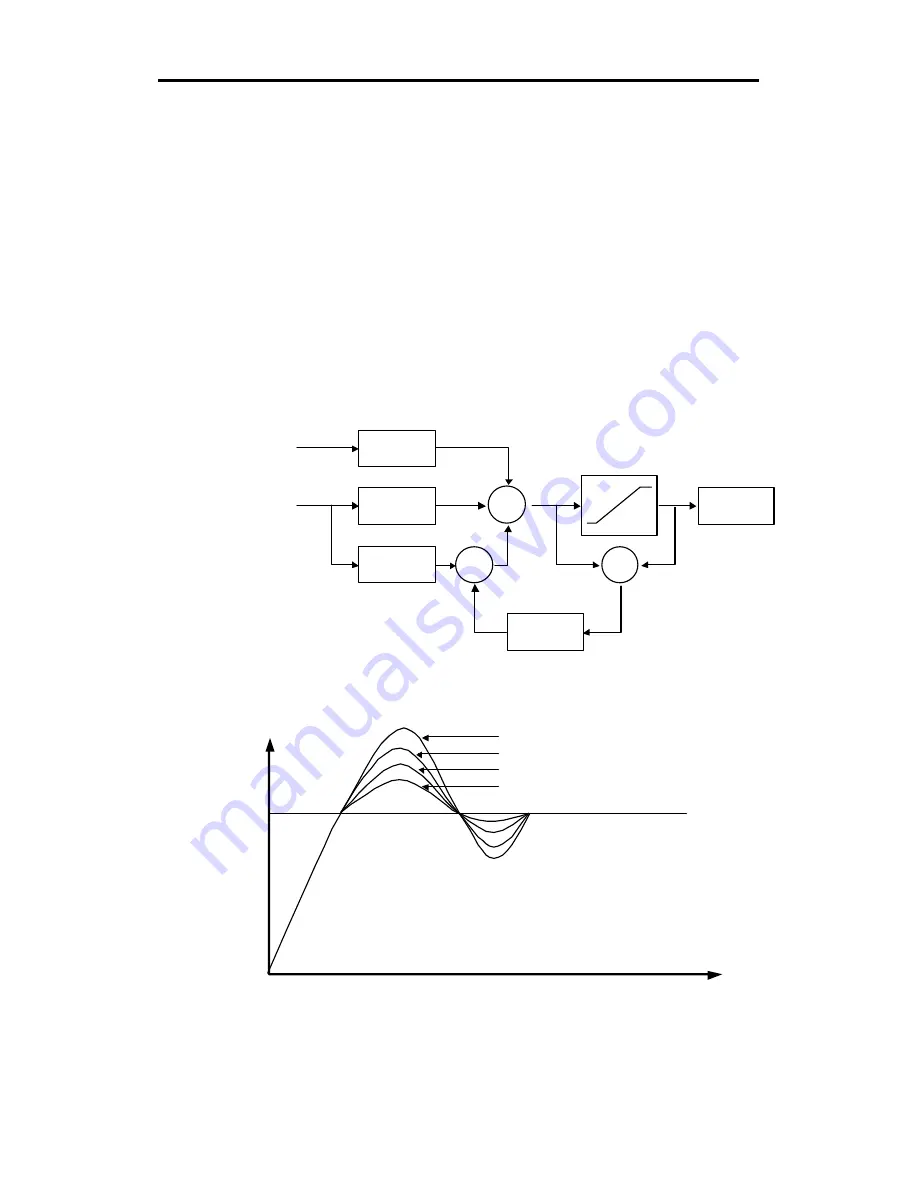
actuator. The Fig. 2-13 shows the block diagram of the anti -windup control system
using the actuator model.
As shown in the Fig. 2-13, the anti-windup system feedback the multiplication of gain
(1/Tt) and Es to the input of integral term. The Es is obtained as the difference value
between actuator output (U) and manipulation value of PID controller (MV). The Tt of
the feedback gain is tracking time constant, and it is in inverse proportion with the
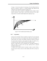
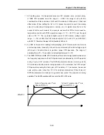
resetting speed of integral term. Smaller Tt will cancel the windup of actuator faster,
but too small Tt can cause anti -windup operation in derivative operation. The Fig. 2 -14
shows several Tt value and PV in the PI control system.
Fig. 2-13 The block diagram of anti-windup control system
Fig. 2-14 The PV output characteristics with different Tt values.
K
×
Td
K
Actuator
1 / Tt
k / Ti
+
+
+
E = SV-PV
E = -PV
MV
U
Actuator model
Es
–
+
Tt = 3
Tt = 2
Tt = 1
Tt = 0.1
Time
PV
SV


