IPECS Release 5
Hardware Description & Installation
Issue 5.0
55
4.3.4 Module Wall Mount Holder Kit
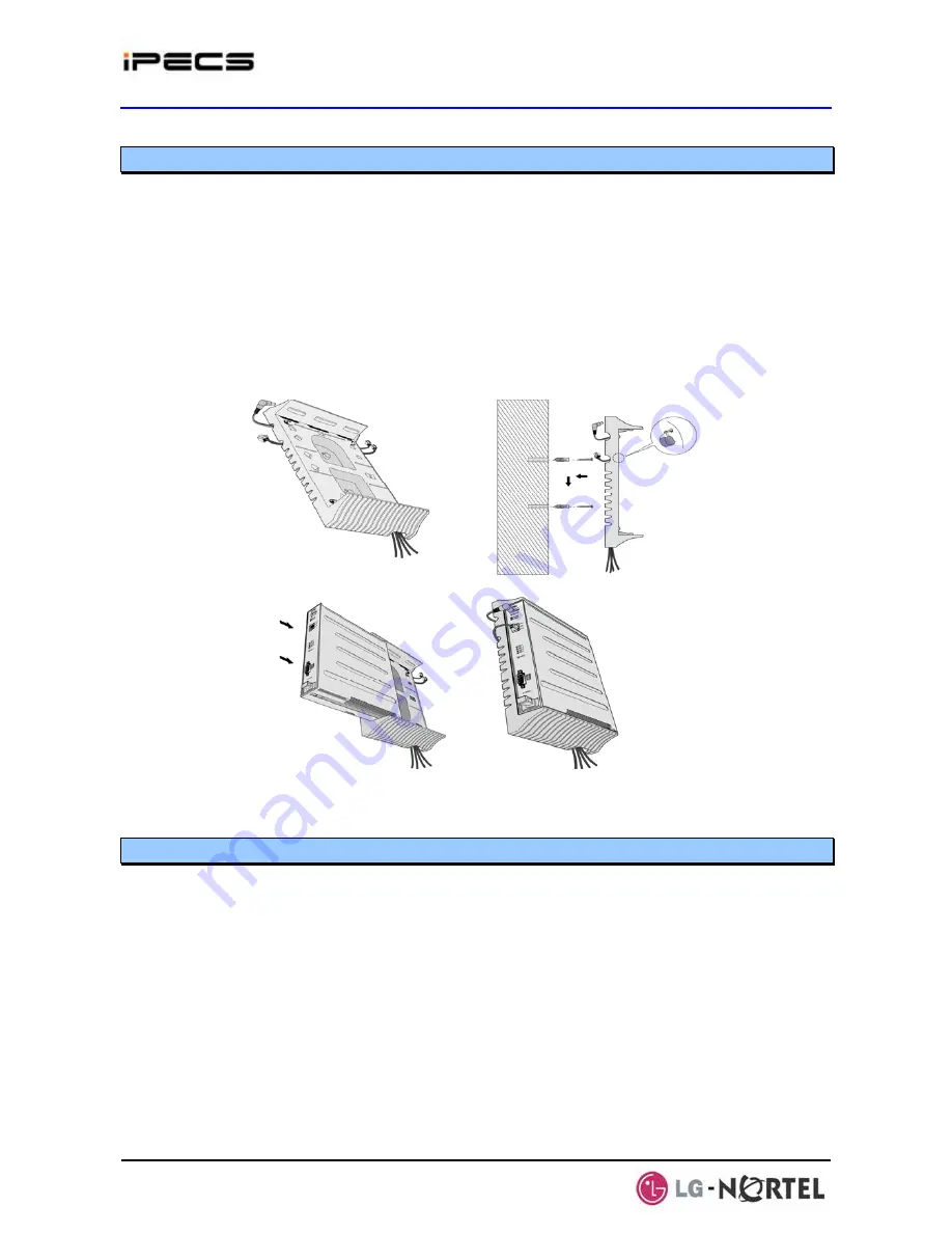
The Module Wall Mount Holder will house a single Module. To install, refer to Figure 4.3.4-1 and
instructions below:
¾
Place the Wall Mount Holder in position and mark two (2) holes over a wall stud.
¾
Drill two (2) 7 mm holes for the plastic wall anchors provided.
¾
Insert the two (2) anchors into the holes, then insert and tighten the 2 screws leaving about
6 mm (¼-inch) exposed.
¾
Arrange wiring on the back of the Wall Mount Holder.
¾
Place (hang) the Wall Mount Holder on the screws and tighten securely.
¾
Slide the Module into the Wall Mount Holder until it locks.
¾
Connect all wiring to the Module as appropriate, refer to section 4.5.
Figure 4.3.4-1 Module Wall Mount Holder Kit
4.3.5 1U-Rack Mount Bracket Installation
The Module 1U-Rack Mount Bracket will house a single Module and an AC/DC adapter to power
the Module. To install, refer to figures and instructions below:
1. Install the AC/DC adapter in the 1U-RMB. Refer to Figure 4.3.5-1.
¾
Remove the two (2) screws on the rear of 1U-RMB to release the upper housing
¾
Lift up and remove the upper housing.
¾
Remove the two (2) screws holding the adapter bracket.
¾
Lift up and remove the adapter bracket
¾
Install an adapter (The label side of the adapter should be placed on the inner surface
of 1U-RMB), place the adapter bracket over the adapter and fasten the two (2) screws.
¾
Insert the adapter DC plug through the hole in the front of 1U-RMB. Note for the
RSGM, the DC cable should exit through the hole in the rear of the 1U-RMB.


