IPECS Release 5
Hardware Description & Installation
Issue 5.0
60
the DB9 connector of the PSU to the gateway Module defined in admin PGM 197. Refer to
Figure 4.4-3. Note when a back-up PSU is installed, the serial cable is connected to the
back-up PSU only. Note that when employing a WTIM as the notifying gateway Module,
Dip switch 3 of the WTIM, the Serial Mode switch, must be set to OFF, the Main CPU Serial
mode.
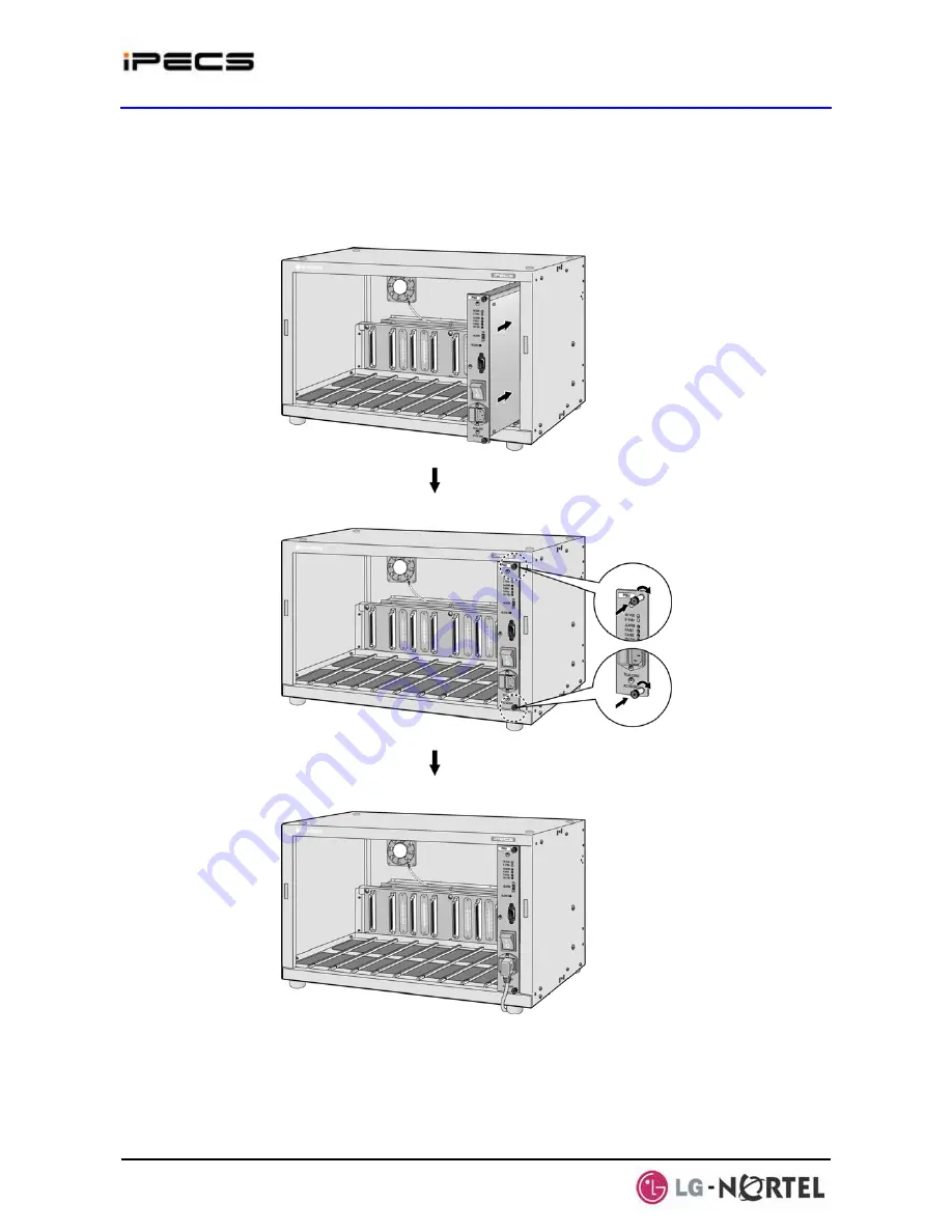
Figure 4.4-1 Main PSU Installation
The back-up PSU for power redundancy is installed as described below and shown in Figure 4.4-2.
¾
Install the main PSU as described above and shown in Figure 4.4-1.


