background image

Copyright © 2009 LG Electronics. Inc. All right reserved.

              - 25 -                                                         

LGE Internal Use Only


Only for training and service purposes           


5.  In case of no sound 


(1) Symptom 

1) LED 

is 

blue. 

2)  Screen display but sound is not output 


(2)  In case of no sound to speaker 


All input mode 

  is no sound? 

Yes 

Is VCC “+12V” 

(JP1:1pin) and L5 normal?

No 

No 

Replace Power 
Board& U2(FET)

Yes 

Is the speaker 
on it Audio 
menu? 

No 

Check the 
Speaker Cable 

Only HDMI is 

no sound? 

Download 

the EDID data. 

No 

Only TV is 

no sound? 

No 

Yes 

Check the Tuner 
In/Out

Yes 

Only AV/PC input is no 

sound? 

No 

Check the input source.

Yes 

Replace Main Board. 

Set on speaker 
in Audio menu


Is the Speaker 
Cable normal? 

Yes 

No 

Only Componet/ DVD 

  input is no sound? 

Is the output of U741 
normal? 

No 

Yes 

Yes 

U112 operate 
normal? 

Replace U112 
(FLI10610H)

U761 operate 
normal? 

Replace U761 
(NTP-3000A)

No 

No 

Yes 

Yes 

Replace Main Board. 

No 

Replace U714 
(CD4052) 

Check the input source &DVD 
player. 

Yes 

Block B 

Summary of Contents for 19LU7000

Page 1: ... Internal Use Only http aic lgservice com http eic lgservice com http biz lgservice com LCD TV SERVICE MANUAL CHASSIS LU7000 MODEL 22LU7000 22LU7000 ZA CAUTION BEFORE SERVICING THE CHASSIS READ THE SAFETY PRECAUTIONS IN THIS MANUAL Printed in Korea ...

Page 2: ...served 2 LGE Internal Use Only Only for training and service purposes CONTENTS CONTENTS 2 SAFETY PRECAUTIONS 3 SPECIFICATION 6 ADJUSTMENT INSTRUCTION 12 TROUBLE SHOOTING 18 BLOCK DIAGRAM 30 WIRING DIAGRAM 31 EXPLODED VIEW 34 SCHEMATIC DIAGRAMME 38 ...

Page 3: ... such as antennas terminals etc to be sure the set is safe to operate without damage of electrical shock Leakage Current Cold Check Antenna Cold Check With the instrument AC plug removed from AC source connect an electrical jumper across the two AC plug prongs Place the AC switch in the on position connect one lead of ohm meter to the AC plug prongs tied together and touch other ohm meter lead in ...

Page 4: ... on your body by touching a known earth ground Alternatively obtain and wear a commercially available discharging wrist strap device which should be removed to prevent potential shock reasons prior to applying power to the unit under test 2 After removing an electrical assembly equipped with ES devices place the assembly on a conductive surface such as aluminum foil to prevent electrostatic charge...

Page 5: ...the solder joints of the two original leads If they are not shiny reheat them and if necessary apply additional solder Fuse and Conventional Resistor Removal Replacement 1 Clip each fuse or resistor lead at top of the circuit board hollow stake 2 Securely crimp the leads of replacement component around notch at stake top 3 Solder the connections CAUTION Maintain original spacing between the replac...

Page 6: ...0 240V 50 60Hz Standard Voltage of each products is marked by models 2 4 Specification and performance of each parts are followed each drawing and specification by part number in accordance with BOM 2 5 The receiver must be operated for about 5 minutes prior to the adjustment 4 General Specification No Item Specification Remark 1 Display Screen Device 19 22 wide Color Display Module 2 Aspect Ratio...

Page 7: ...yne Digital DVB T COFDM 3 SCART Jack 2EA PAL SECAM SCART1 Jack is Full SACRT and support RF OUT TV OUT SCART2 jack is Half SCART and support MNT OUT 4 Video Input RCA 1EA PAL SECAM NTSC Rear 5 Component Input 1EA Y Cb Cr Y Pb Pr 6 RGB Input RGB PC Analog D SUB 15PIN 7 HDMI Input 2EA HDMI1 DTV DVI HDMI2 DTV PC HDMI version 1 3 Support HDCP 8 Audio Input 3EA RGB DVI Audio Component AV L R Input 9 SD...

Page 8: ...imately 30 minutes in a dark environment at 25 3 The values specified are at approximate distance 50Cm from the LCD surface 4 Ta 25 C VLCD 5 0V fV 60Hz fclk 77 0MHz IBL 7 5mA 6 2 22 LCD Module No Item Min Typ Max Unit Remark 1 Luminance white Luminance white 280 350 cd m PSM Vivid CSM Cool White 100 IRE Variation 1 3 2 View angle R L U D 170 155 degree 3 Contrast ratio 700 1000 4 Color Coordinate ...

Page 9: ...tion H freq kHz V freq kHz Pixel clock MHz Proposed Remark 1 720 480 15 73 59 94 13 500 SDTV DVD 480I 525I 2 720 480 15 75 60 00 13 514 SDTV DVD 480I 525I 3 720 576 15 625 50 00 13 500 SDTV DVD 576I 625I 50Hz 4 720 480 31 47 59 94 27 000 SDTV 480P 5 720 480 31 50 60 00 27 027 SDTV 480P 6 720 576 31 25 50 00 27 000 SDTV 576P 50Hz 7 1280 720 44 96 59 94 74 176 HDTV 720P 8 1280 720 45 00 60 00 74 250...

Page 10: ... 59 94 25 175 SDTV 480p 60Hz 2 640 480 31 469 60 25 20 SDTV 480p 60Hz 3 720 480 31 47 59 94 27 00 SDTV 480p 60Hz 4 720 480 31 50 60 27 027 SDTV 480p 60Hz 5 720 576 31 25 50 00 27 00 SDTV 576p 50Hz 6 1280 720 37 50 50 00 74 176 HDTV 720p 50Hz 7 1280 720 44 96 59 94 74 176 HDTV 720p 60Hz 8 1280 720 45 00 60 74 250 HDTV 720p 60Hz 9 1920 1080 28 125 50 00 74 250 HDTV 1080i 50Hz 10 1920 1080 33 72 59 9...

Page 11: ...59 87 80 125 VESA WXGA HDCP 6 1360 768 47 72 59 80 84 625 VESA WXGA HDCP 12 Mechanical specification 12 1 19LU7000 ZA 12 2 22LU7000 ZA No Item Content Unit Remark 1 Product Dimension Width W Length D Height H mm Before Packing 467 5 194 410 2 mm With Stand After Packing 522 218 461 mm Box Out Size 2 Product Weight Only SET 5 1 Kg With Stand With BOX 7 Kg No Item Content Unit Remark 1 Product Dimen...

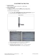
Page 12: ...m TV Software Download a Put the hmx_lu7000_GB hdf UK_Model hmx_lu7000_EU hdf EU_Model in the USB b Connect the USB device to the USB IN jack on the side of the TV 19 22LU7000 ZA c AC Power Off and On the TV d Waiting until the new software upgrade is finished e Finishing the version uploading you have to put USB stick and AC Power off f After putting AC Power on and check updated version on your ...

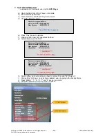
Page 13: ...ng 100 completed CAUTION Do not turn off the player 3 DVD S W DOWNLOAD To update the DVD software use only the DVD Player a Open the Door press Eject keys on a remote b Insert the S W update Disc c Close the Door press Eject keys on a remote d Check the follow message e Press Play keys on a remote f Waiting until the new S W upgrade is finished g Automatically open the Door h Finishing the vesion ...

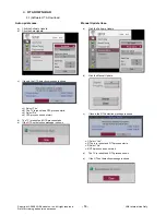
Page 14: ...Yes c 2 The TV is reboot and OTA process starts c 3 Select No c 4 OTA process does not start d The TV is reboot and OTA process starts e If the OTA not detection message is shown Manual Update Case a Click the Software Update b Click the Manual Update c If found the OTA detection message is shown c 1 Select Yes c 2 The tv is reboot and OTA process starts c 3 Select No c 4 OTA process does not star...

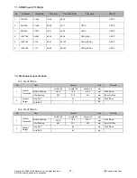
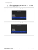
Page 15: ...and service purposes 5 EDID DOWNLOAD 4 1 Panel Setting a You should change the panel size by going to the Factory Mode press Menu 1 2 4 7 and 5 keys on a remote b You have to select 19 22 panel in Factory mode 19LU7000 ZA Panel Select Æ LG_WXGA_LC190WH1 22LU7000 ZA Panel Select Æ LG_WXGA_LC220WXE ...

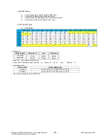
Page 16: ...78 2A 6F B5 A4 55 4D 9B 25 0x20 12 50 54 A1 08 00 31 40 45 40 61 40 01 01 01 01 0x30 01 01 01 01 01 01 66 21 50 B0 51 00 1B 30 40 70 0x40 36 00 9A E6 10 00 00 1E 0E 1F 00 80 51 00 1E 30 0x50 40 80 37 00 9A E6 10 00 00 1C 00 00 00 FD 00 39 0x60 3F 1C 45 0F 00 0A 20 20 20 20 20 20 00 00 00 FC 0x70 D 00 E ⓐ Product ID MODEL NAME PRODUCT ID HEX EDID Table 19LU7000 19379 4B B3 B3 4B 22LU7000 22315 57 2...

Page 17: ...3 23 0x90 09 57 07 83 01 00 00 67 03 0C 00 F 38 2D 01 0xA0 1D 80 D0 72 1C 16 20 10 2C 25 80 C4 8E 21 00 00 0xB0 9E 01 1D 80 18 71 1C 16 20 58 2C 25 00 C4 8E 21 0xC0 00 00 9E 01 1D 00 BC 52 D0 1E 20 B8 28 55 40 C4 0xD0 8E 21 00 00 1E 01 1D 00 72 51 D0 1E 20 6E 28 55 0xE0 00 C4 8E 21 00 00 1E 00 00 00 00 00 00 00 00 00 0xF0 00 00 00 00 00 00 00 00 00 00 00 00 00 00 00 G ⓐ Product ID MODEL NAME PRODU...

Page 18: ...AC Switch Plug in power cord Is connect the AC Switch cable Replace AC switch Is connect the Power Board and 15p of Main Board Cable Connect Cable Replace fuse After remove the cable connect to Power Board except the AC switch cable and Power cord authorizes the AC voltage marking on manual When 5V does not operate Yes No Is plug in power cord Yes No No No Yes Yes AC Switch Value LU7000 Power B D ...

Page 19: ...th the color where the front LED is red from blue 2 Check follow Is normal the Power Board Is normal the each connector Is output the normality Low High voltage Is normal the Main Board Yes Yes No No No No Replace Power Board After connecting well each connector the normality it operates Replace Power Board After remove JP1 normal operation Replace Main Board Is normal the output voltage after rem...

Page 20: ...ccur at screen 2 It maintains the condition where the front LED is blue 2 Check follow Does minute discharge At Module Is the LVDS cable normal Is the U112 FLI10610H Output normal Yes Yes No No No Is output the normality Low High voltage Reconnect the LVDS cable in JP451 No Yes Yes Is the inverter on Replace Main Board Replace Main Board Check the LCD Module ...

Page 21: ...OSD 1 Symptom 1 LED is blue 2 The minute discharge continuously becomes accomplished from module 2 Check follow Is normal the LVDS Cable Is normal the T Con Board of Module Yes No No No Yes Is the LVDS cable connected well Replace Power Board Replace T Con Board or LCD Module Cable inserts well No Yes Operates the U112 FLI10610H Replace Main Board Replace U112 FLI10610H Is normal the main Board Ye...

Page 22: ... In case of becomes unusual display from A V mode 5 In case of becomes unusual display from RGB mode Is normal the Tuner DVB T Analog Is normal the U112 FLI10610H Yes No No No Yes Is the Tuner cable connected well Is normal the Input voltage IIC Communication and AV2 CVBS output Cable inserts well Yes Is normal the Input voltage IIC Communication and HV sync Replace IC or Main Board No Replace Tun...

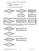
Page 23: ...becomes unusual display from SCART1 mode 9 In case of becomes unusual display from SCART2 mode No Is Hdmi input of HDMI Jack JP621 normal Same as Block A Yes Check the input source No Is Video input of A V Jack JP661 normal Same as Block A Yes Check the input source No Is Video input of A V Jack JP662 normal Same as Block A Yes Check the input source Is Hdmi input of HDMI Jack JP622 normal No Chec...

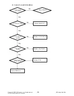
Page 24: ...g and service purposes 10 In case of becomes unusual display from Component mode 11 In case of becomes unusual display from DVD mode Is Y Pb Pr input of the JP743 normal Check the input source No Yes Same as Block A Is Y Pb Pr input of the JP982 normal No Check the DVD Player Same as Block A Yes ...

Page 25: ...r on it Audio menu No Check the Speaker Cable Only HDMI is no sound Download the EDID data No Only TV is no sound No Yes Check the Tuner In Out Yes Only AV PC input is no sound No Check the input source Yes Replace Main Board Set on speaker in Audio menu Is the Speaker Cable normal Yes No Only Componet DVD input is no sound Is the output of U741 normal No Yes Yes U112 operate normal Replace U112 F...

Page 26: ...ce purposes 3 In case of no sound to Headphone All input mode is no sound No Same as Block B Yes Is VCC 3V3 normal No Replace U45 LD1117 Yes U112 operate normal Replace U112 FLI10610H U764 operate normal Replace U764 TPA6110 Yes No No Is sound output of the JP762 normal Yes Replace JP762 Replace MainBoard ...

Page 27: ...nly Only for training and service purposes 6 Exterior view defectiveness 1 Check follow Damage LCD module Replace LCD Module No Damage cabinet No Yes Yes Replace cabinet Yes Damage RCU Replace RCU No Replace stand Scratch Stand Yes Damage DVD Player No Replace DVD Player Yes ...

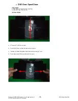
Page 28: ...Door Open Close 1 Symptom 1 Door being not Opened Closed completely 2 Unbalance Open Close the door 2 Check follow a AC power off while door is open b Grab both L R door with each hands and pull it open c If pulled with hands disregard noises heard while opening by force d Doors are opened till its symmetrical to the center ...

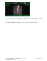
Page 29: ...al Use Only Only for training and service purposes e AC power on and press eject button with remote or with keys and check to make sure that Door is opened or closed f If the Door is not aligned correctly or still not functioning correctly repeat the procedure from a ...

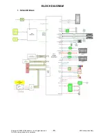
Page 30: ...Copyright 2009 LG Electronics Inc All right reserved 30 LGE Internal Use Only Only for training and service purposes BLOCK DIAGRAM 1 SCALER Block ...

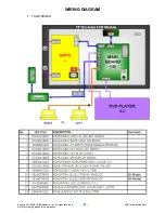
Page 31: ...Copyright 2009 LG Electronics Inc All right reserved 31 LGE Internal Use Only Only for training and service purposes WIRING DIAGRAM 1 19LU7000 ZA ...

Page 32: ...Copyright 2009 LG Electronics Inc All right reserved 32 LGE Internal Use Only Only for training and service purposes 2 22LU7000 ZA ...

Page 33: ...Copyright 2009 LG Electronics Inc All right reserved 33 LGE Internal Use Only Only for training and service purposes MEMO ...

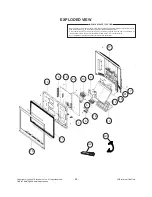
Page 34: ...ical parts in this chassis have special safety related characteristics These parts are identified by in the Schematic Diagram and EXPLODED VIEW It is essential that these special safety parts should be replaced with the same components as recommended in this manual to prevent X RADIATION Shock Fire or other Hazards Do not modify the original design without permission of manufacturer IMPORTANT SAFE...

Page 35: ...Copyright 2009 LG Electronics Inc All right reserved LGE Internal Use Only Only for training and service purposes SCHEMATIC DIAGRAMME 19 22LU7000 ZA ...

Page 36: ...Copyright 2009 LG Electronics Inc All right reserved 39 LGE Internal Use Only Only for training and service purposes ...

Page 37: ...Copyright 2009 LG Electronics Inc All right reserved 40 LGE Internal Use Only Only for training and service purposes ...

Page 38: ...Copyright 2009 LG Electronics Inc All right reserved 41 LGE Internal Use Only Only for training and service purposes ...

Page 39: ...Copyright 2009 LG Electronics Inc All right reserved 42 LGE Internal Use Only Only for training and service purposes ...

Page 40: ...Copyright 2009 LG Electronics Inc All right reserved 43 LGE Internal Use Only Only for training and service purposes ...

Page 41: ...Copyright 2009 LG Electronics Inc All right reserved 44 LGE Internal Use Only Only for training and service purposes ...

Page 42: ...Copyright 2009 LG Electronics Inc All right reserved 45 LGE Internal Use Only Only for training and service purposes ...

Page 43: ...Copyright 2009 LG Electronics Inc All right reserved 46 LGE Internal Use Only Only for training and service purposes ...

Page 44: ...Copyright 2009 LG Electronics Inc All right reserved 47 LGE Internal Use Only Only for training and service purposes ...

Page 45: ...Copyright 2009 LG Electronics Inc All right reserved 48 LGE Internal Use Only Only for training and service purposes ...

Page 46: ...Copyright 2009 LG Electronics Inc All right reserved 49 LGE Internal Use Only Only for training and service purposes ...

Page 47: ...Copyright 2009 LG Electronics Inc All right reserved 50 LGE Internal Use Only Only for training and service purposes ...

Page 48: ...Copyright 2009 LG Electronics Inc All right reserved 51 LGE Internal Use Only Only for training and service purposes ...

Page 49: ...Copyright 2009 LG Electronics Inc All right reserved 52 LGE Internal Use Only Only for training and service purposes ...

Reviews: