background image

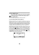
Power(DPMS) Indicator
This Indicator lights up green when the monitor operates
normally. If the monitor is in DPM (Energy Saving) mode (stand-
by/suspend/power off), this indicator color changes to amber.

Power ON/OFF Button
This button is used to turn the monitor on and off.

On Screen Display (OSD) Control Adjustment

Making adjustments to the image size, position and operating
parameters of the monitor are quick and easy with the On Screen
Display Control system, using only the Enter button and Adjustment
Control knob. A quick example is given below to familiarize you with
the use of the controls. Following this section is an outline of the
available adjustments and selections you can make using the OSD.

Note: (Monitor and PC should be ON, with an image or prompt on the
screen.) Rotating the Adjustment Control knob clockwise one click will
present you with the Main Menu of the On Screen Display system,
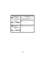
with the first item          highlighted (red color). The main picture area
will also show the selected icon and a brief description (here H-SIZE).
If you turned the control more than one click, a different icon may be
highlighted (red color). Move the control until the       icon is
selected. The OSD system should look like :

A11

S E L :

OSD

: E N T

H   S I Z E

A11

Summary of Contents for 216SC

Page 1: ...Color Monitor USER GUIDE MANUEL D UTILISATION MODEL 216SC ...

Page 2: ...asures Reorient or relocate the receiving antenna Increase the separation between the equipment and the receiver Connect the equipment into an outlet on a circuit different from that to which the receiver is connected Consult the dealer or an experienced radio TV technician for help Caution Changes or modifications not expressly approved by LG Electronics Inc for compliance could void the user s o...

Page 3: ...Environmental Labelling of Personal Computers ii ...

Page 4: ...iii ...

Page 5: ...TCO 95 Environmental Requirements iv ...

Page 6: ... for Disassembly Recycling These monitors have been designed for easy end of life disassembly and recycling Fasteners are generally of the same type for efficient disassembly Components made of different materials can be easily separated and plastics have been identified using intermational symbols to aid in recycling Monitor Disposal WARNING If you need to dispose of a monitor ask a qualified ser...

Page 7: ...ntrol Panel Function OSD Enter Button A10 OSD Select Adjustment Control A10 Brightness Adjustment Control A10 Contrast Adjustment Control A10 Power DPMS Indicator A11 Power ON OFF Button A11 On Screen Display OSD Control Adjustment A11 OSD Adjustment and Selection Items A12 Self Diagnostics and DDC Self Diagnostics A18 DDC Display Data Channel A18 Video Memory Modes Factory Preset Timing Signal Ch...

Page 8: ...ical scan frequencies between 50 and 160 Hz The microprocessor based intelligence allows the monitor to operate in each frequency mode with the precision of a fixed frequency monitor The microprocessor based digital controls allow you to conveniently adjust a variety of image controls by using the OSD On Screen Display The monitor has 32 memory locations for display modes 9 of which are factory pr...

Page 9: ...Model No Serial No Notice All rights reserved Reproduction in any manner in whole or in part is strictly prohibited without the written permission of LG Electronics Inc Trademark Acknowledgments LG is a trademark of LG Electronics Inc IBM is a registered trademark and VGA is a trademark of International Business Machines Corporation WARNING To reduce the risk of fire or electric shock do not expos...

Page 10: ...ed on the monitor If you are not sure what type of power supply you have in your home consult your dealer 3 Overloaded AC outlets and extension cords are dangerous So are frayed power cords and broken plugs They may result in a shock or fire hazard Call your service technician for replacement 4 DO NOT OPEN THE MONITOR There are no user serviceable components inside There are Dangerous High Voltage...

Page 11: ...ors are provided with ventilation openings in the cabinet to allow the release of heat generated during operation If these openings are blocked built up heat can cause failures which may result in a fire hazard Therefore NEVER Block the bottom ventilation slots by placing the monitor on a bed sofa rug etc Place the monitor in a built in enclosure unless proper ventilation is provided Cover the ope...

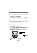
Page 12: ...r allow for a wide variety of video controllers to be connected to the monitor Examples of signals that might be sent to the monitor include signals from IBM PC and compatibles Apple Macintosh Centris Quadra and SPARC workstations The supplied signal cable consists of 15 pin VGA connectors at both ends suitable for connections to an IBM PC or compatible Other generic cables or adapters may be used...

Page 13: ...he 15 pin VGA connector of the supplied signal cable to the output VGA video connector on the PC and the matching input connector on the rear of the monitor The connectors will mate only one way If you cannot attach the cable easily turn the connector upside down and try again When mated tighten the thumbscrews to secure the connection 3 Power ON the PC then the monitor 4 If you see the NO SIGNAL ...

Page 14: ...C to VGA adapter block at your local computer store This adapter changes the high density 3 row 15 pin VGA connector to the correct 15 pin 2 row connection to mate with your MAC Attach the other end of the signal cable to the side of the adapter block with 3 rows 4 Connect the attached adapter block signal cable to the video output on your MAC 5 Power ON the PC then the monitor 6 If you see the NO...

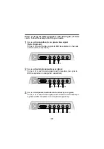
Page 15: ...nitor respectively 2 In case of external composite sync signal Connect R G and B video signals and Composite sync signal to BNC receptacles on rear panel respectively 3 In case of separate horizontal and vertical sync signals Connect R G and B video signals and horizontal and vertical sync signals to BNC receptacles on rear panel respectively A8 R G B H V V Red Green Blue R G B H V V Red Green Blu...

Page 16: ... Front View OSD Select Adjustment Control BNC Signal Connectors AC Power Socket D Sub Signal Connector ID Label Power DPMS Indicator Rear View Power ON OFF Button OSD Enter Button Brightness Adjustment Control Contrast Adjustment Control ...

Page 17: ... a single click will back you out to the Main Menu display and then will exit the menu OSD Select Adjustment Control Use this knob for selecting highlighting an OSD icon to be adjusted It is also used for selecting the level of the selected item to be adjusted Brightness Adjustment Control Used to adjust the brightness of the screen Move the thumbwheel located beneath this indicator to increase or...

Page 18: ...quick example is given below to familiarize you with the use of the controls Following this section is an outline of the available adjustments and selections you can make using the OSD Note Monitor and PC should be ON with an image or prompt on the screen Rotating the Adjustment Control knob clockwise one click will present you with the Main Menu of the On Screen Display system with the first item...

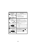
Page 19: ...s the screen image right To adjust image width Decreases the size of the screen image Increases the size of the screen image A D J OSD H S I Z E 1 2 0 1 2 8 0 x 1 0 2 4 7 5 H z A D J OSD H P O S I T I O N 1 2 0 1 2 8 0 x 1 0 2 4 7 5 H z Vertical Size Vertical Position To move image up and down Moves the screen image up Moves the screen image down To adjust image height Decreases the size of the sc...

Page 20: ... screen image wider at the top To correct image rotation Tilts the screen image left Tilts the screen image right This control adjusts for a skewing of the screen image Tilts the screen image rightward Tilts the screen image leftward A D J OSD OSD S I D E P I N 1 2 0 1 2 8 0 x 1 0 2 4 7 5 H z A D J OSD T R A P E Z O I D 1 2 0 1 2 8 0 x 1 0 2 4 7 5 H z A D J OSD T I L T 1 2 0 1 2 8 0 x 1 0 2 4 7 5 ...

Page 21: ...e To select color temperature 9300K 7200K USER Select the desired color temperature or select user to set your own color levels Allow for specific adjustments to Red and Blue R B This consists of the Decreases and Increases function Decreases the amount of color in the image Increases the amount of color in the image A D J OSD Z O O M A D J U S T O U T I N A D J E N T OSD C O L O R S E L E C T 930...

Page 22: ...an Line with the periodical dot screen It is normally OFF If you want to adjust it select ON using the adjustment control and push the Enter Button This item gives access 5 elements Manual Degaussing Beep ON OFF Signal Input Video Level and Exit Press the Enter Button to select the desired item to change Used to demagnetize the picture to give a move account image and color To select Beep ON or Be...

Page 23: ... desired video mode information The mode information screens give you some information regarding industry resolution terminology resolution and memory mode number M O D E R E C A L L M O D E N O 6 1 2 8 0 x 1 0 2 4 N O R E C A L L M O D E M O D E N O 1 5 9 5 k H z 7 2 H z S E L E N T OSD M O D E I N F O R M A T I O N M O D E I N F O W S 1 2 8 0 X 1 0 2 4 P R E S E T M O D E 8 U S E R M O D E 1 M O...

Page 24: ...guage in which the control names are displayed OSD Menus are available in five language English German French Spanish and Italian To disappear of the OSD on the screen S E L OSD L A N G U A G E S E L E C T E N D E F R E S I T E N G L I S H S E L E N T OSD O S D T U R N O F F ...

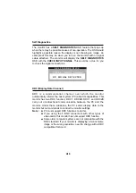
Page 25: ...rms the host system PC about its capabilities This monitor has two DDC function DDC1 DDC2B DDC1 and DDC2B carry out uni directional communication between the PC and the monitor Under these situations the PC sends display data to the monitor but not commands to control the monitor settings Note PC must support DDC functions to do this If you using the 5 BNC connectors with other types of video card...

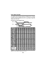
Page 26: ...71 3 657 3 725 3 040 3 023 2 844 2 765 6 356 Front Porch uS 0 636 0 323 0 203 0 508 0 320 0 119 0 406 0 316 0 636 Pulse Width uS 3 813 1 616 1 219 1 016 1 280 1 067 1 016 0 948 3 813 Back Porch uS 1 907 3 232 2 235 2 201 1 440 1 837 1 422 1 501 1 907 Polarity Frequency Hz 59 941 75 000 75 029 84 997 75 062 75 025 85 024 75 000 70 087 Total Period mS 16 683 13 333 13 328 11 765 13 322 13 329 11 761...

Page 27: ...mode 9 Recalling Display Modes When your monitor detects a mode it has seen before it automatically recalls the image settings you may have made the last time you used that mode You may however manually force a recall of each of the eight preset modes by pressing the Recall button All preset modes are automatically recalled as the monitor senses the incoming signal The ability to recall the preset...

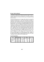
Page 28: ...mption during periods of non use When the PC goes into the energy saving mode the monitor will go into a suspended operation state indicated by the Power LED light changing from a green color to an amber color After an extended period in the suspended mode the monitor will then enter a semi OFF mode to conserve more energy In the semi OFF mode or DPMS OFF mode as we call it in our specifications t...

Page 29: ... monitor Monitor Input Limits Horizontal 30 96 kHz Vertical 50 160Hz The signal cable is incorrectly configured or connected refer to the page Signal Connector Pin Assignment for reference Try power code OFF and ON A new mode is selected User control has not yet been adjusted Use the controls to adjust image Refer to Location and Function of controls Self diagnostics message on back raster appear ...

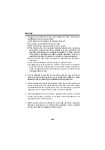
Page 30: ...nt while the monitor is operating It is normal for some monitors to make occasional sounds when being turned on or off or when changing video modes 2 Do not attempt to service the monitor yourself as opening or removing covers may expose you to dangerous voltage or other hazards Refer all servicing to qualified service personnel 3 When replacement parts are required have the service technician ver...

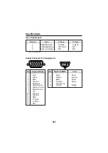
Page 31: ...e H Sync H or H V V sync Pin 1 2 3 4 5 N C No Connection 1 2 3 Separate Sync Composite Sync Sync On Green H Sync H V Sync N C V Sync N C N C Priority Type H Sync V Sync Pin Signal D Sub Pin Signal 5 BNC Color Red Green Blue Ground Self Test Red Ground Green ground Blue Ground NC Ground Ground SDA H Sync V Sync SCL 1 2 3 4 5 6 7 8 9 10 11 12 13 14 15 ...

Page 32: ...ative Composite Positive Negative Signal Input 15pin D Sub Connector 5 BNC Connector Video Input Display Area 390 x 290 mm 15 35 x11 4 inches HxV Input Form Separate RGB Analog 0 7Vp p 75 ohm SOG Sync On Green Power Input AC 100 120 200 240 V 60 50 Hz 2 0 1 0 A Dimensions with tilt swivel stand Width 498 mm 19 6 inches Height 510 mm 20 0 inches Depth 516 mm 20 3 inches Weight Net 31 0 kg 68 34 lbs...

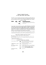
Page 33: ... lasts so these limitations or exclusions may not apply to you This warranty gives you specific legal rights and you may also have other rights which vary from state to state THE ABOVE WARRANTY DOES NOT APPLY U To damages or problems which result from delivery or improper installation U To damages or problems which result from misuse abuse accident alteration or incorrect electrical current or vol...

Reviews: