background image

- 5 -

Copyright © 2010 LG Electronics. Inc. All right reserved.
Only for training and service purposes

LGE Internal Use Only

IC Remove/Replacement

Some chassis circuit boards have slotted holes (oblong) through
which the IC leads are inserted and then bent flat against the
circuit foil. When holes are the slotted type, the following technique
should be used to remove and replace the IC. When working with
boards using the familiar round hole, use the standard technique
as outlined in paragraphs 5 and 6 above.

Removal

1.  Desolder and straighten each IC lead in one operation by gently

prying up on the lead with the soldering iron tip as the solder
melts.

2.  Draw away the melted solder with an anti-static suction-type

solder removal device (or with solder braid) before removing the
IC.

Replacement

1.  Carefully insert the replacement IC in the circuit board.
2.  Carefully bend each IC lead against the circuit foil pad and

solder it.

3.  Clean the soldered areas with a small wire-bristle brush.

(It is not necessary to reapply acrylic coating to the areas).

"Small-Signal" Discrete TransistorRemoval/Replacement

1.  Remove the defective transistor by clipping its leads as close as

possible to the component body.

2.  Bend into a "U" shape the end of each of three leads remaining

on the circuit board.

3.  Bend into a "U" shape the replacement transistor leads.
4.  Connect the replacement transistor leads to the corresponding

leads extending from the circuit board and crimp the "U" with
long nose pliers to insure metal to metal contact then solder
each connection.

Power Output, Transistor Device
Removal/Replacement

1.  Heat and remove all solder from around the transistor leads.
2. Remove the heat sink mounting screw (if so equipped).
3.  Carefully remove the transistor from the heat sink of the circuit

board.

4.  Insert new transistor in the circuit board.
5. Solder each transistor lead, and clip off excess lead.
6.  Replace heat sink.

Diode Removal/Replacement

1.  Remove defective diode by clipping its leads as close as

possible to diode body.

2.  Bend the two remaining leads perpendicular y to the circuit

board.

3.  Observing diode polarity, wrap each lead of the new diode

around the corresponding lead on the circuit board.

4.  Securely crimp each connection and solder it.
5. Inspect (on the circuit board copper side) the solder joints of

the two "original" leads. If they are not shiny, reheat them and if
necessary, apply additional solder.

Fuse and Conventional Resistor
Removal/Replacement

1.  Clip each fuse or resistor lead at top of the circuit board hollow

stake.

2.  Securely crimp the leads of replacement component around

notch at stake top.

3.  Solder the connections.

CAUTION:

Maintain original spacing between the replaced

component and adjacent components and the circuit board to
prevent excessive component temperatures.

Circuit Board Foil Repair

Excessive heat applied to the copper foil of any printed circuit
board will weaken the adhesive that bonds the foil to the circuit
board causing the foil to separate from or "lift-off" the board. The
following guidelines and procedures should be followed whenever
this condition is encountered.

At IC Connections

To repair a defective copper pattern at IC connections use the
following procedure to install a jumper wire on the copper pattern
side of the circuit board. (Use this technique only on IC
connections).

1.  Carefully remove the damaged copper pattern with a sharp

knife. (Remove only as much copper as absolutely necessary).

2. carefully scratch away the solder resist and acrylic coating (if

used) from the end of the remaining copper pattern.

3.  Bend a small "U" in one end of a small gauge jumper wire and

carefully crimp it around the IC pin. Solder the IC connection.

4. Route the jumper wire along the path of the out-away copper

pattern and let it overlap the previously scraped end of the good
copper pattern. Solder the overlapped area and clip off any
excess jumper wire.

At Other Connections

Use the following technique to repair the defective copper pattern
at connections other than IC Pins. This technique involves the
installation of a jumper wire on the component side of the circuit
board.

1.  Remove the defective copper pattern with a sharp knife.

Remove at least 1/4 inch of copper, to ensure that a hazardous
condition will not exist if the jumper wire opens.

2. Trace along the copper pattern from both sides of the pattern

break and locate the nearest component that is directly
connected to the affected copper pattern.

3. Connect insulated 20-gauge jumper wire from the lead of the

nearest component on one side of the pattern break to the lead
of the nearest component on the other side.
Carefully crimp and solder the connections.

CAUTION:

Be sure the insulated jumper wire is dressed so the

it does not touch components or sharp edges.

Summary of Contents for 24MB35D

Page 1: ...R SERVICE MANUAL North Latin America http aic lgservice com Europe Africa http eic lgservice com Asia Oceania http biz lgservice com CAUTION BEFORE SERVICING THE UNIT READ THE SAFETY PRECAUTIONS IN THIS MANUAL CHASSIS NO LM14E MODEL Internal Use Only 24MB35D ...

Page 2: ...right reserved Only for training and service purposes LGE Internal Use Only CONTENTS CONTENTS 2 PRECAUTION 3 SERVICING PRECAUTIONS 4 SPECIFICATIONS 6 TIMING CHART 11 ADJUSTMENT 14 BLOCK DIAGRAM 18 TROUBLE SHOOTING 19 EXPLODED VIEW 22 SVC SHEET ...

Page 3: ...he module from the ESD as it may damage the electronic circuit C MOS Make certain that treatment person s body are grounded through wrist band Do not leave the module in high temperature and in areas of high humidity for a long time The module not be exposed to the direct sunlight Avoid contact with water as it may a short circuit within the module If the surface of panel become dirty please wipe ...

Page 4: ...any electrostatic charge on your body by touching a known earth ground Alternatively obtain and wear a commercially available discharging wrist strap device which should be removed to prevent potential shock reasons prior to applying power to the unit under test 2 After removing an electrical assembly equipped with ES devices place the assembly on a conductive surface such as aluminum foil to prev...

Page 5: ...the solder joints of the two original leads If they are not shiny reheat them and if necessary apply additional solder Fuse and Conventional Resistor Removal Replacement 1 Clip each fuse or resistor lead at top of the circuit board hollow stake 2 Securely crimp the leads of replacement component around notch at stake top 3 Solder the connections CAUTION Maintain original spacing between the replac...

Page 6: ...g Picture Mode Six Color Factory Gamma Calibration 7 Power Cord Length 1 87 m Shape Wall out Color Black Refer to Suffix standard and power cord table 8 Cable Signal Cable D SUB Length 1 8m Shape Detachable Type Color Black Pin Triple Row 15 Pin D Sub Refer to Suffix standard DVI Length 2 0m Shape Detachable Type Color Black Pin Triple Row 18 Position DVI D Refer to Suffix standard Audio Length Co...

Page 7: ...30 Luminance Uniformity 75 min 3 Contrast Ratio 명암 비 600 MIN 1000 TYP DFC 5 000 000 1 Typ 4 Response Time Gray to Gray 8ms middle 5 Reader mode Reader1 x 0 335 0 395 y 0 330 0 390 Reader2 x 0 323 0 383 y 0 337 0 397 No Item Content Remark 1 Product Dimension Width W Length D Height H Before Packing 56 9 21 0 43 3 with Stand cm 56 9 6 4 34 2 Without Stand cm After Packing 63 9 41 4 13 9 Unit cm 2 P...

Page 8: ...ttage On Mode On On Active White After about 15s turn to Off 31W Typ Test condition 1 1920x1080 60Hz 2 burst pattern 3 100 240V 4 After aging 30mi On On Super Energ y saving off Active White After about 15s turn to Off 36W Max Sleep Mode Off On On Off Off Off Off White Blinking 0 3W under Off Mode Power switch off Off 0 3W under 7 Super Energys Saving Low High Off low White SES saving low 2w h 10 ...

Page 9: ...HERS LANGUAGE ENGLISH 17 Language English Germanic FACTORY RESET NO French Spanish Italian Swedish Finnish Portuguese Polish Brazil Russian Greek Chinese Japanese Korean Ukrainian Hindi MENU AV TV block CHANNEL CHANNEL 2 69 AIR 1 125 CABLE Function Support No ADD DEL CH ADD DELETE AUTO CHANNEL ON OFF SELECT AIR CABLE FINE TUNE 0 100 ADJUSTMEN T CONTRAST 0 100 Function Support No BRIGHTNESS 0 100 S...

Page 10: ... Temperature Setting is 6500 K if it s not special specification Clock Clock Phase The Best Setting z Another Spec Product Specification Standard LG 55 G1 1034 z Cosmetic Spec LCD Module IIS Spec 2 CIE Color Coordinates 색 좌표 Minimum Normal Maximum White WX Typ 0 03 0 283 Typ 0 03 Cool 9300K WY 0 298 White WX Typ 0 03 0 301 Typ 0 03 Medium 8000K WY 0 310 WX Typ 0 03 0 313 Typ 0 03 Warm 6500K WY 0 3...

Page 11: ...ta 128 Bytes 6 2 1 1 EDID Ver 1 3 FOR ANALOG 128Byte 6 2 1 2 EDID Ver 1 3 FOR DIGITAL 128Byte No Item Content 16진 Data 1 Manufacturer ID GSM 1E 6D 2 Product ID Analog 23112 Digital 23113 48 5A 49 5A 3 Year 2014 18 4 Version 1 01 5 Revision Analog 3 Digital 3 03 03 6 Serial Number 7 Week 8 Model Name 24MB35 9 Check Sum 10 Special Item Need to Input Serial Number ...

Page 12: ...0 128 88 800 x 600 V Lines 60 317 628 600 1 4 23 5 H Pixels 49 5 46 875 1056 800 16 80 160 800 x 600 V Lines 75 0 625 600 1 3 21 6 H Pixels 65 0 48 363 1344 1024 24 136 160 1024 x 768 V Lines 60 0 806 768 3 6 29 7 H Pixels 78 75 60 023 1312 1024 16 96 176 1024 x 768 V Lines 75 029 800 768 1 3 28 8 H Pixels 108 0 67 500 1600 1152 64 128 256 1152 x 864 V Lines 75 000 900 864 1 3 32 9 H Pixels 108 0 ...

Page 13: ...gnal to RJ 45 input with LAN cable connected network devices such as routers Check USB 1 1 Port Keyboard Mouse RJ 45 input Check USB 2 0 Port USB Memory Stick 2port RJ 45 input Check Audio Ear phone out Mic in Speaker RJ 45 input PC audio volume MAX LAN cable Router PC vSpace S W for N Ver 4 5 xx xx Caution Ver 4 4 xx xx for N1742L family 3 2 2 Total Assembly Line Ready Heat run during5 minutes in...

Page 14: ...M Setting Confirm with Service OSD Confirm at Service OSD by Menu Power key on from Power off Confirm first set of new lot by periods and confirm periodically when there is Process change or Adjustment setting change 3 2 5 5 OSD Adjustment device Confirmation Confirm operation mentioned as product spec Vary Brightness and Contrast and confirm the variation of Luminance and display status Operate t...

Page 15: ... 6 Ergonomics ISO9241 CRT ISO9241 3 7 8 NO ISO13406 2 LCD ISO13406 2 ISO9241 307 NO 7 Etc Korea KC SAFETY Electric Supplies Safety Rule K60950 No KC EMC MIC Ordinance 825 MIC Notice 100 Class B Electric Article Technical Standard Ⅲ YES 8 Etc China CCC GB4943 GB9254 GB17625 1 YES 9 Test Hi Pot 1500 V ac or 2121Vdc 1 sec under 10mA No Earth Continuity 25 A 1 sec under 0 1 ohm No 10 EPA 6 0 EnergySta...

Page 16: ... 4 Cross hatch pattern Horizontal 10Line Vertcial 8Line Rectangle Pattern Pattern 5 1 Dot on 1 Dot off Rectangle Pattern Pattern 6 Vertical Sync only input Use signal cable of which Pin 5 is GND Pattern 7 Horizontal Sync only input Use signal cable of which Pin 5 is GND Pattern 8 State of without Vertical Horizontal Sync and Video Signal Use signal cable of which Pin 5 is GND Pattern 9 8 Color Bar...

Page 17: ...BLOCK DIAGRAM Main Copyright 2010 LG Electronics Inc All right reserved Only for training and service purposes LGE Internal Use Only 17 ...

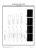
Page 18: ...raining and service purposes LGE Internal Use Only 1 NO POWER 18 No power issue Check P100 PIN 1 Is IC102 PIN2 12V PIN3 5V CHECK LIPS CHECK IC102 Is IC 103 PIN2 3 3V CHECK IC103 Is IC100 PIN48 PIN49 PULSE CHECK CRYSTAL X100 YES YES YES NO NO NO NO CHECK IC100 IC102 1 IC102 2 IC103 X100 ...

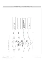
Page 19: ... IS NOT DISPLAYED MAIN 19 No Raster OSD is not displayed Check P103 PIN1 5V IC100 PIN48 49 14 318MHz 1 CHECK IC102 PIN3 5V 2 Check Q107 Q105 1 CHECK X100 2 Trouble in IC100 CHECK IC100 PIN32 H SYNC PIN33 V SYNC CHECK IC100 YES YES YES NO NO NO Trouble in cable or LCD module CHECK CONNECTION From DSUB TO IC100 Change IC100 YES NO ...

Page 20: ...ll right reserved Only for training and service purposes LGE Internal Use Only 3 TROUBLE IN DPM 20 CHECK H V SYNC LINE Trouble in DPM IC100 PIN32 33 CHECK PC PC is going to the DPM mode YES YES NO NO Trouble in IC100 Check R127 AND R128 ...

Page 21: ...Schematic Diagram and EXPLODED VIEW It is essential that these special safety parts should be replaced with the same components as recommended in this manual to prevent X RADIATION Shock Fire or other Hazards Do not modify the original design without permission of manufacturer IMPORTANT SAFETY NOTICE 920 400 200 300 410 330 540 910 320 310 460 450 ...

Page 22: ...98 AVDD_GDPWR 99 VDET0 100 STR0 101 GND_LED_1 102 STR1 103 VDET1 104 VDET2 105 STR2 106 GND_LED_2 107 STR3 108 VDET3 109 VDDC_2 110 VCTRL GPIO56 111 VDDP_7 112 GND_7 113 GPIO21 RS232_RX1 114 GPIO20 RS232_TX1 115 SAR0 GPIO_SAR0 116 SAR1 GPIO_SAR1 117 SAR2 GPIO_SAR2 118 SAR3 GPIO_SAR3 119 GPIO22 PWM4 120 GPIO23 PWM5 121 GPIO24 PWM6 122 GPIO25 PWM7 123 GPIO26 SAR4 124 GPIO27 SAR5 125 GPIO30 126 GPIO3...

Page 23: ...VA207 ADUC 20S 02 010L 20V R209 4 7K VA201 5 5V ADUC 5S 02 0R5L DSUB_DET R227 10 C205 68pF C202 68pF 5VS VA200 5 5V ADUC 5S 02 0R5L DVI_HPD VA210 20V ADUC 20S 02 010L READY GREEN R231 33 R225 10 RED DVI_SDA R235 10K 1 16W 5 R210 4 7K VA202 5 5V ADUC 5S 02 0R5L R221 10 IC201 M24C02 RMN6T 3 E2 2 E1 4 VSS 1 E0 5 SDA 6 SCL 7 WC 8 VCC BLUE JP_GND1 JP_GND3 JP_GND4 JP_GND2 D202 RCLAMP0524PA OPT ESD_HDMI_...

Page 24: ......

Reviews: