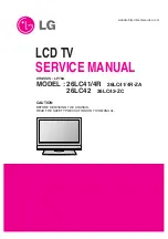
background image

R

LCD TV

SERVICE MANUAL

CAUTION

BEFORE SERVICING THE CHASSIS,
READ THE SAFETY PRECAUTIONS IN THIS MANUAL.

CHASSIS : LP78A

MODEL : 26LC41/4R

26LC41/4R-ZA

MODEL : 

26LC42

26LC42-ZC

website:http://biz.LGservice.com

Summary of Contents for 26LC41/4R

Page 1: ...R LCD TV SERVICE MANUAL CAUTION BEFORE SERVICING THE CHASSIS READ THE SAFETY PRECAUTIONS IN THIS MANUAL CHASSIS LP78A MODEL 26LC41 4R 26LC41 4R ZA MODEL 26LC42 26LC42 ZC website http biz LGservice com ...

Page 2: ... 2 CONTENTS CONTENTS 2 SAFETY PRECAUTIONS 3 SPECIFICATION 6 ADJUSTMENT INSTRUCTION 9 TROUBLE SHOOTING 17 BLOCK DIAGRAM 25 EXPLODED VIEW 26 EXPLODED VIEW PARTS LIST 27 REPLACEMENT PARTS LIST 28 SVC SHEET ...

Page 3: ...Current Cold Check Antenna Cold Check With the instrument AC plug removed from AC source connect an electrical jumper across the two AC plug prongs Place the AC switch in the on position connect one lead of ohm meter to the AC plug prongs tied together and touch other ohm meter lead in turn to each exposed metallic parts such as antenna terminals phone jacks etc If the exposed metallic part has a ...

Page 4: ...vely obtain and wear a commercially available discharging wrist strap device which should be removed to prevent potential shock reasons prior to applying power to the unit under test 2 After removing an electrical assembly equipped with ES devices place the assembly on a conductive surface such as aluminum foil to prevent electrostatic charge buildup or exposure of the assembly 3 Use only a ground...

Page 5: ...not shiny reheat them and if necessary apply additional solder Fuse and Conventional Resistor Removal Replacement 1 Clip each fuse or resistor lead at top of the circuit board hollow stake 2 Securely crimp the leads of replacement component around notch at stake top 3 Solder the connections CAUTION Maintain original spacing between the replaced component and adjacent components and the circuit boa...

Page 6: ...H x V x D with inverter H x V H x V x D with inverter H x V LC260WX2 SLB3 LPL 26 Specification 26 27 32 37 42 wide Color Display Module 16 9 26 27 32 37 42 TFT WXGA LCD Temp 0 40 deg Humidity 0 85 Temp 20 60 deg Humidity 0 85 100 240V 50 60Hz Power on Green TBD 42 max 26 27 32 37 St By Red 1 0 W AUO Outline Dimension 26 32 37 Pixel Pitch 26 32 37 Back Light 26 32 37 CMO Outline Dimension 27 32 Pix...

Page 7: ...00 Proposed SDTV DVD 480I 525I SDTV DVD 480I 525I SDTV DVD 576I 625I 50Hz SDTV 480P SDTV 480P SDTV 576P 50Hz HDTV 720P HDTV 720P HDTV 720P 50Hz HDTV 1080I HDTV 1080I HDTV 1080I 50Hz H freq kHz 15 73 15 75 15 625 31 47 31 50 31 25 44 96 45 00 37 50 33 72 33 75 28 125 Resolution 720 480 720 480 720 576 720 480 720 480 720 576 1280 720 1280 720 1280 720 1920 1080 1920 1080 1920 1080 Pixel clock MHz 1...

Page 8: ...P 50Hz HDTV 1080I HDTV 1080I HDTV 1080I 50Hz HDTV 1080P HDTV 1080P HDTV 1080P 50Hz H freq kHz 15 75 15 73 15 625 31 47 31 50 31 25 44 96 45 00 37 50 33 72 33 75 28 125 67 432 67 5 56 250 Resolution 720 480 720 480 720 576 720 480 720 480 720 576 1280 720 1280 720 1280 720 1920 1080 1920 1080 1920 1080 1920 1080 1920 1080 1920 1080 Pixel clock MHz 13 514 13 500 13 500 27 000 27 027 27 000 74 176 74...

Page 9: ...stment items 3 1 PCB assembly adjustment items 1 Download the VCTP main software IC500 VCT_Pro 2 Channel memory IC501 EEPROM 3 Color carrier Adjustment 3 2 SET assembly adjustment items 1 DDC Data input 2 Adjustment of White Balance 3 Factoring Option Data input 4 PCB assembly adjustment method Using VCTP Download program 4 1 Download program installation 1 Extract a Zip file 2 Visual I2C LPT Driv...

Page 10: ...Connect the download jig to D sub jack 2 Execute Download vi2c program in PC then a main window will be opened 3 Double click the blue box and confirm Bootloader Version as 42 4 Click the Erase Flash button 5 Double click the download file low then edit window will be opened 6 Click the choice button in the edit window then file choice window will be opened 7 Choose the Hex file in folder and exec...

Page 11: ...ad jig to D sub jack 2 Supply the power Stand by 5V and wait for 3 seconds 3 Push the S W off Disconnect SCL to GND using switch at jig 4 Execute Download vi2c program in PC then a main widow will be opened 5 Double click the blue box and confirm Bootloader Version as 42 6 Click the Erase Flash button 7 Double click the download file low then edit window will be opened 8 Chick the choice button I ...

Page 12: ...wnload method 3 SET 1 Push the Tilt button in an Adjust Remocon Then the LCD TV will change a slave mode 2 Connect Zig to TV using a D sub cable 3 Execute Download_CS vi2c program in PC then a main widow will be opened 4 Click GO button If you don t push the go the Hex file would not be downloaded although the download proceeds normally at first glance 5 Double click the blue box and confirm Bootl...

Page 13: ...ick OK button at the edit window 11 Downloading 12 If download is failed for example No acknowledge from slave execute download again from 1 4 3 Channel memory download 1 Connect the download jig to D sub jack 2 Execute Channel vi2c program in PC then a main window will be opened 3 Push the button change and select the Channel memory data 4 Check the communication is OK or not Push the Read area A...

Page 14: ...lor Bar MA NTSC Digital Pattern with color Bar 2 push the adj key in the adjustment remocon 5 EDID The Extended Display Identification Data DDC Display Data Channel download Caution Use the proper signal cable for EDID Download Never connect HDMI D SUB Cable at the same time Use the proper cables below for EDID Writing EDID Data EDID DATA Analog Set 128bytes EDID DATA HDMI Set 256bytes Tool Option...

Page 15: ...ustment 6 2 Connecting diagram of equipment for measuring For Automatic Adjustment 1 Enter the DDC adjust mode Enter the DDC adjust mode at the same time heat run mode when pushing the power on by power only key Enter the adjust mode and change the input mode to AV ZA AV3 TA MA AV2 when pushing the Front av key Maintain the DDC adjust mode with same condition of Heat run Maintain after AC off on i...

Page 16: ... Mode Standard ZA TA Optimum MA Color Temp Normal Normal 9300K x 0 283 0 003 y 0 298 0 003 Luminance Y AV upper 150 cd m2 Typ 350 cd m2 Reference Value Automatically fixed Cool 11000K x 0 274 0 003 y 0 286 0 003 Warm 7200K x 0 303 0 003 y 0 319 0 003 Pattern for Adjustment of White Balance 7 When adjustment is completed Exit adjustment mode using EXIT key on R C 6 4 Input the Shipping Option Data ...

Page 17: ...wer cord plugged in Connect the cable SC100 No Yes Are the line filter and PSU connected Replace the fuse No Yes Is the correct fuse for the PSU in place LCD F100 Connect the 13 14pin cable Next remove all cables connected to the PSU and switch the AV voltage to manual If the ST by 5V does not operate replace the PSU No Yes Is the PSU and 13 14pin cable connected to the VSC board ...

Page 18: ...operate correctly Yes No No Is the Y Board normal Is the appropriate fuse FS2 FS3 on the Y B D Is the output voltage normal after removing the P1 connector of the Y B D Yes No No Replace the Z Board Is the Z Board normal Is appropriate fuse FS1 FS2 on the Z B D Is the output voltage normal after removing the P1 connector of the Z B D Yes No No Is the X Board normal Is the output voltage normal aft...

Page 19: ...al Low High voltage except for the Stand by 5V Yes No No Is there a fault with the link cable Yes Is the output for the IC500 normal Reconnect the link cable in P804 No Replace the VSC No Yes Check the power L1103 Is the video output of the Tuner normal Check TU400_Pin13 Is the input voltage normal Check Pin3 Is the I2C communication normal Check Pin9 Pin10 Yes No Yes Is the LVDS Cable connected Y...

Page 20: ...nput source No 6 In the case of an unusual display in Side AV mode Is the video input of the A V jack normal Check CN703 Pin9 Yes Sam as Block A Check the input source No 7 In the case of an unusual display in Side S Video mode Is the video input of the A V jack normal Check CN703 Pin1 Pin3 Yes Sam as Block A Check the input source No ...

Page 21: ...e input source No 9 In the case of an unusual display in SCART 1_RGB mode Is the video input of the A V jack normal Check R110 R170 R171 R173 Yes Sam as Block A Check the input source No 10 In the case of an unusual display in SCART 2 mode Is the video input of the A V jack normal Check R174 Yes Sam as Block A Check the input source No ...

Page 22: ...t source No 12 In the case of an unusual display in component 2 mode Yes Change the IC IC500 Check the input source No Is the video input of the A V Jk202 normal Check R241 R242 R243 13 In the case of an unusual display in RGB mode Yes Change the IC IC500 Check the input source No Is the R G B input and H V sync of the JK201 normal Check R220 R221 R253 R254 R255 ...

Page 23: ...ere no sound only AV COM2 PC Is the output of IC600 R607 R608 normal Yes Is there no sound only for RF No No No No Download the EDID data Set speaker on in the menu No Replace the IC600 No Check the Speaker cable No Is the IC500 operating normal Replace the IC500 No Yes Is the IC601 operating normal Replace the IC601 Replace the VSC BD Yes Check the signal after IC600 Refer to circuit diagram Chec...

Page 24: ...thentication attempted Reset TMDS power down on register 0x60 offset 0x3f 0xff Check HDMI source Change to another source or cable Yes Is the wave continuous Normal video Normal audio No Yes Replace the IC303 No 1 Check TV input mode HDMI 1 port support HDMI and DVI So if you input DVI signal and PC audio from phone jack You can hear PC audio 2 Unplug and plug in the HDMI cable sometimes ESD surge...

Page 25: ... 25 HDMI BLOCK DIAGRAM ...

Page 26: ... 26 EXPLODED VIEW 300 200 201 580 520 400 581 582 430 120 600 530 590 591 206 150 202 203 204 205 ...

Page 27: ......

Page 28: ......

Page 29: ......

Page 30: ...Mar 2007 Printed in Korea P NO MFL36696906 ...

Reviews: