1. Scope of Application
These adjustment instructions are applicable to CW91A
Chassis whether SET(0), SKD(0), or CKD(0).
2. Notes
2.1 Because this is a cold chassis, it is not necessary to use
an isolation transformer. However,operating it using a
transformer between the power supply line and chassis
input to prevent electric shock and to protect the test
instrument.
2.2 All adjustments must be done in correct sequence.
However, for better productivity, it can be changed in a pre-
permitted range.
2.3 Environment conditions: If not specified, it must be done in
following conditions.
1) Temperature: 25°C ±5°C
2) Humidity : 65%±10%
2.4 Power supply of SET
1) NTSC
Latin America/Philippines Market:100~240V ±10%,50/60Hz
Korea Market : 220V ±10%,60Hz
Taiwan Market : 110V ±10%,60Hz
Japan Market : 100V ±10%,50/60Hz
2) PAL/SECAM
China/Indonesia/Thailand/Vietnam/CIS Market :
100~240V ±10%, 50/60Hz
2.5 If not specified, the receiver must be operated for more
than 20 minutes prior to the adjustment.
2.6 Signal: Received the standard color signal. (65dB±1dBuV)
NTSC: LG standard signal means the digital pattern
13CH(480NC).
PAL/SECAM: LG standard signal means the digital
pattern PAL-B/Gz 05CH
2.7 If not specified, APC ON is APC CLEAR (DYNAMIC).
3. Adjustment content
3.1. Screen Voltage Adjustment
3.1.1.Adjustment (Use factory remote control)
(1) Input in the 75
Ω
cable LG standard signal
(Digital Pattern,480NC)
(2) Press IN-START KEY and ADJ KEY of SVC T/X
generate horizontal line for Screen adjust.
(3).Turn the screen volume on the FBT clockwise until the
horizontal line is visible and turn it counterclockwise until
horizontal line faintly visible.
(Exit screen voltage adjustment by press “Exit” key of SVC
T/X.)
3.2. Purity and Convergence Adjustment
3.2.1. Purity adjustment
(1). Adjustment Preparation
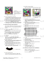
a. Received Red Raster Pattern for purity adjustment (51CH).
b. Demagnetize the CPT and Cabinet with a degaussing coil.
(2). Adjustment
a. Pre-adjust the static convergence(STC) with the 4 and
6-pole magnet.
b. If the horizontal Line is inline with CPT Mark,2-Pole
magnet should direct 3-9 o’clock direction.
c. If not,direct 2-Pole magnet handle toward 6-12 o’clock
direction and adjust the Horizontal Line to fall onto the
mark opening the magnet at an angle.
d.Push the DY(deflection yoke) all the way to the CPT funnel.
e.Turn the purity magnet(2-pole magnet) so that the “green”
color portion of left side and the “blue” color portion on
the right side have equal amount of color.
f.Pull the DY slowly backward and fix it when the whole
screen becomes red.
(The specified torque for fixing DY screw should be 10Kg/cm.)
3.2.2. Convergence adjustment
(1). Necessary Instrument
a. Degaussing Coil
b. Convergence fixing instrument(special tools)
(2). Adjustment Preparation
a. Operate the unit at the least 15 minutes before adjustment.
b. Using degaussing coil,remove the stains on CPT & Cabinet.
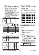
c. Received the Cross Hatch Pattern for Convergence (09ch).
d. Let the Contrast in normal luminance level.
(3). Static Convergence (STC) Adjustment
a. Received the Cross Hatch Pattern for Convergence (09ch).
b. Before adjusting Static Convergence(STC),adjust the
focus first seeing to it that the WHITE color picture quality
is sharp enough.
c. Converge the RED vertical line and BLUE vertical line in
unity(same line) by changing the angle between the 2
tabs of 4-pole magnet.
d. Converge the RED horizontal and BLUE horizontal line
unity(same line) by turning the 2 tabs of the 4-pole magnet.
At this time,do not change the angle between the 2 tabs.
e. Converge the R,G,B vertical line in unity(same line) by
changing the angle between the 2 tabs of the 6-pole magnet.
f. Converge the R,G,B horizontal line in unity(same line) by
turning the 2 tabs of the 6-pole magnet. At this time, do not
change the angle between the 2 tabs.
(4). Dynamic Convergence (DYC) Adjustment
a. Y-Axis Adjustment :Adjust convergence of Y-axis(vertical)
by moving the deflection yoke(DY) left and right.
b. X-axis Adjustment : Adjust convergence of X-axis(horizontal)
by moving the deflection yoke(DY) up and down.
3.3. White Balance Adjustment
3.3.1. Necessary Instrument
(1). Auto white balance meter (Low/High Light Pattern generator)
(2). CRT Color Analyzer, CA-100 :1 set
(3). Factory Remote control
3.3.2. Adjustment preparation : Prior to this adjustment, the
Screen Voltage adjustment should be finished.
3.3.3. Auto Adjustment
(1). Adjust using Auto White Balance Meter.
(2).Enter
CPU OFF
mode by press the “IN-START” &”MUTE”
key of factory remote control in turn before adjustment.
Exit
CPU OFF
mode by press the “MUTE” key of factory
remote control after adjustment finished.
In case there is excess RED color at screen voltage
adjustment, adjust it using “Volume -(
F
)”Key of factory remote
control until the RED color disappear.
- 5 -
ADJUSTMENT INSTRUCTIONS
Copyright©2010 LG Electronics.Inc. All right reserved.
Only for training and service purposes.
LGE Internal Use Only
G
R
B
G
R
B
G
R
B
R
tu2522 tu2522 tu2522 tu2522 tu2522 tu2522 tu2522 tu2522 tu2522 tu2522 tu2522 tu2522 tu2522 tu2522 tu2522 tu2522 tu2522 tu2522 tu2522 tu2522
tu2522 tu2522 tu2522 tu2522 tu2522 tu2522 tu2522 tu2522 tu2522 tu2522 tu2522 tu2522 tu2522 tu2522 tu2522 tu2522 tu2522 tu2522 tu2522 tu2522
tu2522 tu2522 tu2522 tu2522 tu2522 tu2522 tu2522 tu2522 tu2522 tu2522 tu2522 tu2522 tu2522 tu2522 tu2522 tu2522 tu2522 tu2522 tu2522 tu2522
tu2522 tu2522 tu2522 tu2522 tu2522 tu252


