background image

Copyright©2009 LG Electronics.Inc. All right reserved.
Only for training and service purposes.

LGE Internal Use Only

- 20 -

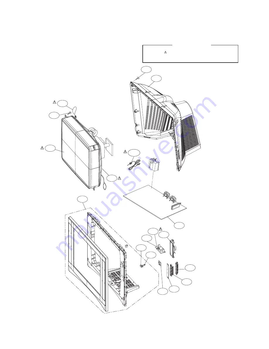
EXPLODED VIEW

300

120

540

311

310

530

330

590

320

504

 174

112

150

170

913

400

943

520

Many electrical and mechanical parts in this chassis have special safety-related characteristics.These
parts are identified by     in the Schematic Diagram and EXPLODED VIEW.
It is essential that these special safety parts should be replaced with the same components as
recommended in this manual to prevent X-RADIATION,Shock, Fire, or other Hazards.
Do not modify the original design without permission of manufacturer. 

IMPORTANT SAFETY NOTICE

Summary of Contents for 29FU1RL

Page 1: ...EAD THE SAFETY PRECAUTIONS IN THIS MANUAL CHASSIS CW62C MODEL 29FU1RL MODEL 29FU1RL T1 Apr 2009 Printed in China P NO MFL37773222 North Latin America http aic lgservice com Europe Africa http eic lgservice com Asia Oceania http biz lgservice com Internal Use Only ...

Page 2: ...r frequency 41 25 MHz Color Sub carrier frequency 42 17 MHz Center frequency 44 MHz CHASSIS CONSTRUCTION IC Solid state chassis PICTURE TUBE Type No A68ERS870X SOUND OUTPUT 10W CABINET Plastic ABBREVIATIONS Used in this book ADJ Adjustment or Adjust AFC Automatic Frequency Control AGC Automatic Gain Control AMP Amplifier CRT Cathode Ray Tube DEF Deflection DET Detector FBT Flyback Transformer H V ...

Page 3: ...e exceeds specified limits check each component specified on the chassis schematic and take corrective action 2 Read and comply with all caution and safety related notes on or inside the receiver cabinet on the receiver chassis or on the picture tube 3 Design Alteration Warning Do not alter or add to the mechanical or electrical design of this TV receiver Design alterations and additions including...

Page 4: ...ADJ key in LINE SVC mode IN START KEY the mode changes to Horizontal Line mode for screen adjustment 3 Adjust the SCREEN at disappear point Horizontal Line using SCREEN VOL of FBT Press the Exit button to exit SVC mode 4 2 Adjustment of White Balance Manually NOTE When adjusting white balance automatically connect the adjustment JIG in LINE SVC MODE When pressing IN START MUTE key on remote contro...

Page 5: ...V AMPITUDE NTSC signal Adjust so that the circle of a digital circle pattern may be located within the effective screen of the CPT 8 H SHIFT HS Adjust so that the vertical center line of a digital circle pattern is in accord with geometric vertical center of the CPT 9 EW WIDTH EW Adjust to that a digital circle pattern looks like exact circle 10 EW PARAB EW PARABOLA Adjust so that middle portion o...

Page 6: ...0 22 34 33 55 13 45 55 35 32 35 21 25 7 2 0 0 1 MENU Vertical slope Vertical shift Vertical linearity Vertical amplitude Horizontal shift EW width Parabola adj Trapezoid adj Upper corner adj Lower corner adj Bow Horizontal parallelogram S correction Vertical scroll Vertical zoom Timing of Wide Blanking Timing of Wide Blanking Vertical slicing level Over voltage input mode Vertical guard mode Yes Y...

Page 7: ...ION ADAPT OVER MODULATION THRESHOLD ADC LEVEL 16 15 ADCLEV DEC LEVEL 16 15 DECLEV MONO LEVEL 16 15 MONOLEV SAP LEVEL 16 15 SAPLEV FILTER BANDWIDTH MTS LEVEL 16 15 MTSLEV AUX3 VOL SCART1 RF SOUND OUT FM WINDOW FILTER FMWS BOOSTER MAX VOLUME DCXO VALUE DCXO ALIGNMENT GAME ADC LEVEL 0 30 DESCRIPTION REMARK Middle South America Korea Table 4 SERVICE 3 AGC RG GG BG BLO R BLO G CDL L DLY RGB BRI 29 32 3...

Page 8: ...D HPOS CAP HPOS CHSE ACL MENU WHITE STRETCH BLACK STRETCH BLACK STRATCH DEPTH DYNAMIC SKIN CONTROL VIDEO DEPENDENT CORING PEAKING FREQUENCY DELAY RATION POSITIVE NEGATIVE PEAKS RATION PRE AFTER SHOOT PEAK WHITE LIMITER DAC IF DEMODULATIOR OSD H POSITION CAPTION H POSITION CHROMA SENSITIVITY AUTO COLOR LIMITING DESCRIPTION 1 1 0 0 2 0 3 2 8 37 5 13 0 1 Middle South America Korea ...

Page 9: ...7 7MHz which is same as frequency in OSD 4 Check out whether a signal generating to MAIN SPEAKER generates in earphone or receiver or not 5 There is no alternation and setting of adjusted DATA in the process of inspecting FM TX OPTION1 OPTION2 OPTION3 OPTION4 0 29 Slim 1 29 Flat 2 29 Normal 3 29 TS AK 0 Other CPT 1 TS AK CPT 0 W O SCR50 1 W SCR50 0 1 TUNER 1 2TUNER 0 W O Video Mute 1 W Video Mute ...

Page 10: ...m the bell of the picture tube and then slide the yoke completely forward 5 Reconnect the internal degaussing coil 6 Position the beam bender locking rings at the 9 o clock position and the other three pairs of tabs 2 4 and 6 pole magnets at the 12 o clock position 7 Perform the following steps in the order given to prepare the receiver for the purity adjustment procedure a Face the receiver in th...

Page 11: ...ussing and then turn the receiver off again 8 Unplug the internal degaussing coil 9 Turn on the receiver connect a signal generator to the VHF antenna terminal and apply a crosshatch signal Caution During the convergence adjustment procedure be very careful not to disturb the purity adjustment tabs are accidentally move purity should be confirmed before proceeding with the convergence adjustments ...

Page 12: ...n the horizontal left to right motion to converge the red and blue horizontal lines Fig upper right 17 Temporarily place a rubber wedge at the 5 o clock and 7 o clock positions to hold the horizontal position of the yoke 18 Check the 3 o clock and 9 o clock areas to confirm that the red and blue vertical lines are converged If the lines are not converged slightly offset the horizontal tilt of the ...

Page 13: ...SVC REMOCON 13 Copyright 2009 LG Electronics Inc All right reserved Only for training and service purposes LGE Internal Use Only ...

Page 14: ...d Only for training and service purposes LGE Internal Use Only 14 TROUBLE SHOOTING Check the waveform at pin 2 4 of IC601 Check the voltage at pin 5 7 of IC601 Check the waveform at pin 8 9 11 12 of IC601 Check IC901 P403A Check FR901 P403A P902B FR401 ...

Page 15: ...Copyright 2009 LG Electronics Inc All right reserved Only for training and service purposes LGE Internal Use Only 15 ...

Page 16: ...G Electronics Inc All right reserved Only for training and service purposes LGE Internal Use Only 16 P20A R G B out of IC501 check IC501 pin 83 84 85 R G B out check IC501 pin 83 84 85 R G B out P20A R G B out of IC501 ...

Page 17: ...Copyright 2009 LG Electronics Inc All right reserved Only for training and service purposes LGE Internal Use Only 17 N P 2 4 8 9 11 2 5 7 Does the auto Program operate properly ...

Page 18: ...Copyright 2009 LG Electronics Inc All right reserved Only for training and service purposes LGE Internal Use Only 18 BLOCK DIAGRAM ...

Page 19: ...Copyright 2009 LG Electronics Inc All right reserved Only for training and service purposes LGE Internal Use Only 19 MEMO ...

Page 20: ... and mechanical parts in this chassis have special safety related characteristics These parts are identified by in the Schematic Diagram and EXPLODED VIEW It is essential that these special safety parts should be replaced with the same components as recommended in this manual to prevent X RADIATION Shock Fire or other Hazards Do not modify the original design without permission of manufacturer IMP...

Page 21: ...P N EBY37965601 ...

Page 22: ...MAIN Copyright 2009 LG Electronics Inc All right reserved Only for training and service purposes LGE Internal Use Only LED POWER CONTRL ...

Reviews: