background image

THERMAL

THERMAL

THE    SYMBOL MARK OF THIS SCHEMETIC DIAGRAM INCORPORATES
SPECIAL FEATURES IMPORTANT FOR PROTECTION FROM X-RADIATION.
FILRE AND ELECTRICAL SHOCK HAZARDS, WHEN SERVICING IF IS 
ESSENTIAL THAT ONLY MANUFATURES SPECFIED PARTS BE USED FOR
THE CRITICAL COMPONENTS IN THE    SYMBOL MARK OF THE SCHEMETIC.

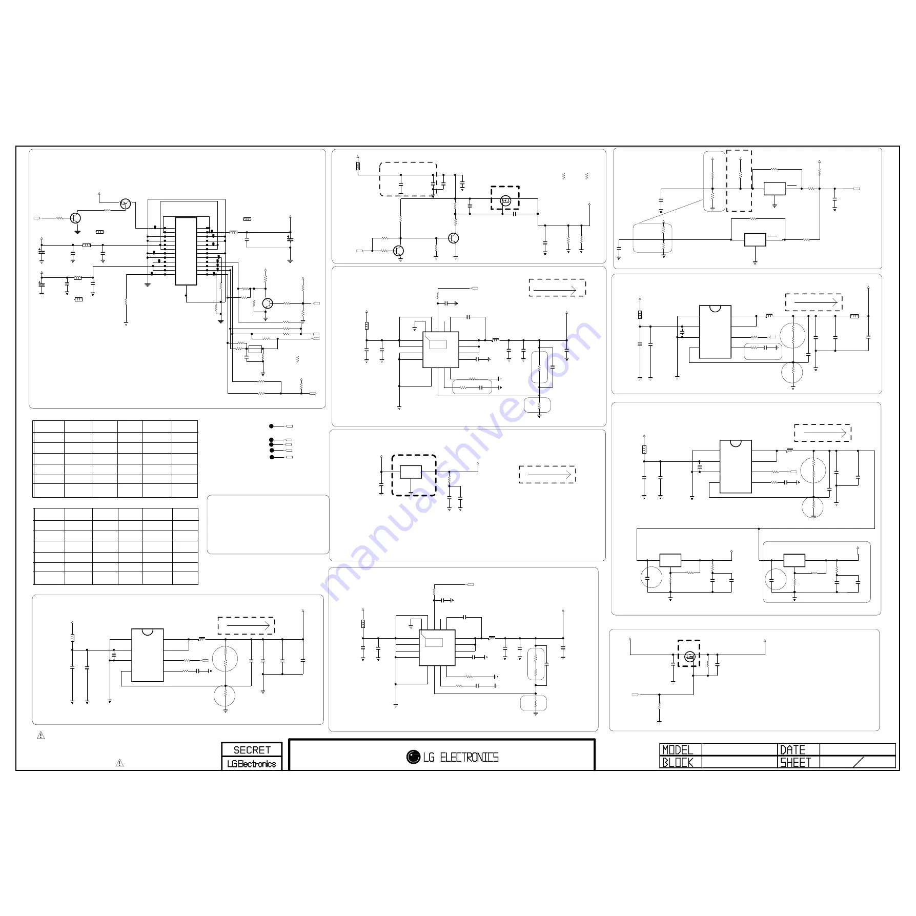
C462

0.1uF

16V

C432
0.1uF
16V

R452

330K

1/16W

5%

IC406

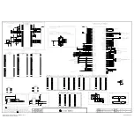
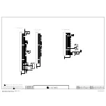
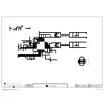
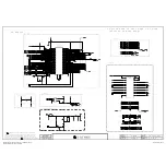
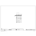
AOZ1072AI-3 

3

AGND

2

VIN

4

FB

1

PGND

5

COMP

6

EN

7

LX_1

8

LX_2

R480
100

PD_+12V

PANEL_VCC

TP5302

C477
0.1uF
16V

C470
0.1uF
16V

C411
0.1uF
16V

V_SYNC

R486

4.7K

OPT

Q408
AO3438

FRC

G

D

S

R440 5.6K

C405
10uF
25V

C476
22uF

10V

R455
15K

1/16W

5%

C416
0.1uF

16V

OPT

C423

100pF

50V

OPT

C413

2200pF

L422

3.6uH

NR8040T3R6N

PWM_DIM

C463
100pF
50V

C441

0.1uF

16V

R476

0

POWER_23_GND

R431

22K

R449
56K

1/16W

1%

+3.5V_ST

C427

100pF

50V

OPT

R445

10K

C407

0.1uF
16V

OPT

C430
10uF
10V

ERROR_OUT

+3.3V_Normal

+3.5V_ST

L420

A_DIM

C431
0.1uF
16V

L413

SCAN_BLK1/OPC_OUT

L417

R407
2.2K

OPT

L412

+3.3V_Normal

R462

10K

1%

C420
22uF
16V

R459

10K

R606

3.9K

PWM_PULL-DOWN_3.9K

Q402

RT1P141C-T112

1

2

3

R439

33K

C461
10uF
10V

C473
0.1uF
16V

Q409

AO3407A

G

D

S

R415
100

POWER_18_INV_CTL

R416

1.5K

1%

C455
0.1uF
16V

R485

0

POWER_22_A_DIM

R419
1K

R456

10K

Q406
2SC3052

E

B

C

R464

10K

P403

FW20020-24S

NORMAL_EXPEPT_32

19

14

9

4

18

13

8

3

17

12

7

2

16

11

6

1

20

15

10

5

21

22

23

24

P401
SMAW200-H24S2

SLIM_32~52

19

12V

14

GND

9

3.5V

4

24V

18

INV ON

13

GND

8

GND

3

24V

17

12V

12

3.5V

7

GND

2

24V

16

GND/V-sync

11

3.5V

6

GND

1

PWR ON

20

A.DIM

15

GND

10

3.5V

5

GND

21

12V

22

P.DIM1

23

GND/P.DIM2

24

Err OUT

25

+12V/+15V

C438
0.1uF
16V

IC401

AOZ1073AIL-3 

3

AGND

2

VIN

4

FB

1

PGND

5

COMP

6

EN

7

LX_1

8

LX_2

R457

47K

1%

C410
10uF
25V

R414

51K

1%

R404

100K

PD_+12V

POWER_ON/OFF2_2

INV_CTL

POWER_ON/OFF2_1

+24V

C451

0.1uF
50V

OPT

1608

R443

10K

FRC

C428
0.1uF
16V

OPT

C408
0.1uF
16V

OPT

R488
100K

L416

TP5305

+12V/+15V

POWER_DET

Q401
2SC3052

E

B

C

R461

4.7K

1%

POWER_ON/OFF2_2

PANEL_CTL

1:AK10

OPC_OUT

+12V/+15V

R401

10K

L415

3.6uH

NR8040T3R6N

C440
0.1uF
16V

C401

100uF

16V

R427

10K

OPT

R463

10K

OPT

0

R484

POWER_20_PWM_DIM

C474
0.1uF

R475

0

POWER_24_GND

R460

27K

1%

R406
4.7K

+2.5V_Normal

C453
22uF

10V

POWER_ON/OFF1

R458

12K

+1.5V_FRC_DDR

C468
0.1uF
16V

C445

4.7uF

OPT

TP5304

SCAN_BLK2

C435
4.7uF

10V

OPT

L423

3.6uH

NR8040T3R6N

+12V/+15V

+3.5V_ST

C406
0.1uF
16V

C444
0.1uF
16V

R405
2.2K

OPT

POWER_ON/OFF2_1

C472
22uF

10V

+3.5V_ST

R426
10K

OPT

R434

120K

OPT

R436
7.5K

1/16W

5%

R473

1

R432

330K

1/16W

5%

OLP

C475

0.1uF

16V

L404

MLB-201209-0120P-N2

C404

0.1uF

16V

R467

10K

1%

C439

100pF

50V

L401

C467

4700pF

50V

+24V

+3.5V_ST

R444

22K

1

%

+5V_USB

+3.3V_Normal

R410

10K

C412
0.1uF
16V

PD_+12V

RL_ON

+1.5V_DDR

L424

CIC21J501NE

R453

0

POWER_20_A_DIM

+3.5V_ST

+12V/+15V

TP5303

C448

3300pF

50V

Q407
2SC3052

E

B

C

L407

MLB-201209-0120P-N2

+3.3V_Normal

100

R437

POWER_20_ERROR_OUT

R451

0

POWER_18_A_DIM

+3.5V_ST

POWER_ON/OFF2_1

R421
10K

R442

24K

1%

C403
10uF
10V

C402

100uF

16V

P404

FM20020-24

NORMAL_32

19

14

9

4

18

13

8

3

17

12

7

2

16

11

6

1

20

15

10

5

21

22

23

24

25

C442

10uF
16V

OPT

R425
100

POWER_24_INV_CTL

0

R471

POWER_22_PWM_DIM

C426

68uF
35V

R402
100

C436

0.01uF

25V

0.01uF

L406

3.6uH

NR8040T3R6N

R412

0

POWER_16_GND

+12V/+15V

C424
0.1uF
16V

R429
47K

C485
0.1uF
16V

IC402

AZ2940D-2.5TRE1

2

GND

3

VOUT

1

VIN

R441
75K

1/8W

1%

Q405

2SC3052

E

B

C

R430
10K

OPT

+1.26V_VDDC

C418

0.1uF

50V

R435

22K

L421

3.6uH

NR8040T3R6N

R423

10K

1%

R418

6.8K

OPT

C447

0.1uF

16V

IC405

AOZ1073AIL-3 

3

AGND

2

VIN

4

FB

1

PGND

5

COMP

6

EN

7

LX_1

8

LX_2

C456
22uF

10V

0

R472

POWER_24_PWM_DIM

100

R420

POWER_24_ERROR_OUT

+1.5V_DDR

C429

100pF

50V

OPT

TP5306

C466

2200pF

IC409

NCP803SN293

PD_+12V_PWR_DET_ON_SEMI

1

GND

3

VCC

2

RESET

IC408

NCP803SN293

PWR_DET_ON_SEMI

1

GND

3

VCC

2

RESET

IC407

TPS54319TRE

1

VIN_1

3

GND_1

7

COMP

9

SS/TR

10

PH_1

11

PH_2

12

PH_3

13

BOOT

14

PWRGD

15

EN

16

VIN_3

5

AGND

8

RT/CLK

6

VSENSE

4

GND_2

2

VIN_2

17

EP[GND]

R450

0

5%

PD_+3.5V

R482

8.2K

1%

24V

R403

1.5K

1%

24V

C465

0.01uF

50V

C488

0.01uF

50V

L402

MLB-201209-0120P-N2

L402-*1

CIS21J121

L404-*1

CIS21J121

L407-*1

CIS21J121

R448

2.7K

1%

PD_+12V

R447

1.21K

1/10W

1%

PD_+12V

C443
10uF

25V

C457
10uF
25V

C458
10uF
25V

C459
10uF
25V

C460
10uF
25V

C409
0.015uF
50V

0.015uF

R454

12K

R413

12K

C469
22uF
16V

C464

2200pF

IC403

SN1007054RTER

1

VIN_1

3

GND_1

7

COMP

9

SS

10

PH_1

11

PH_2

12

PH_3

13

BOOT

14

PWRGD

15

EN

16

VIN_3

5

AGND

8

RT/CLK

6

VSENSE

4

GND_2

2

VIN_2

17

EP[GND]

R606-*1

1K

PWM_PULL-DOWN_1K

R465

24K

1%

R466

51K

1%

C471
22uF
16V

R424

1

5%

IC410

AP1117EG-13 

ADJ/GND

OUT

IN

+5V_Normal

IC411

AP1117EG-13 

ADJ/GND

OUT

IN

R422

1

5%

C417
0.1uF
16V

R408

110

C414
0.1uF
16V

R417

110

C491
0.1uF
50V

C422
0.1uF
50V

C415

10uF
10V

C419

10uF
10V

R409

330

R411

330

C489
0.1uF
16V

C490
0.1uF
16V

+5V_TUNER

C492
0.1uF
16V

R405-*1

3K

PANEL_DISCHARGE_RES

R407-*1

3K

PANEL_DISCHARGE_RES

16

R1

PIN No

LGD edge led error-out use or not? checking is necessary...

INV_ON

New item

26/32/52:GND

24V-->3.78V --> 3.92V (3.79V)

2000 mA

INV_ON

26/32/52:PWM

NC

CMO10"LED

NC

GND

err_out

(PSU)

Vout=(1+R1/R2)*0.8

3A

NC

GND

<LED MODULE PIN MAP -> latest update 20100618>

$ 0.145

err_out

23

GND

GND

18.5V-->3.5V --> 3.75V (3.59V)

NC

SHARP

err_out

INV_ON

err_out

AUO 10"Lamp

NC

4A

INV_ON

A-DIM

MAX 1A

Vout=0.8*(1+R1/R2)

LGD LPB/ 

+3.5V_ST -> 3.375V

23

<MODULE PIN MAP>

INV_ON

GND

+3.3V_Normal

or LIPS

PANEL_POWER

NC

CMO10"Lamp

+5V_Normal

S7M DDR 1.5V

26/32HD:NC

S7M core 1.26V volt

(PSU)

NC

INV_ON

Err_out

PWM_DIM

NC

22

(PSU)

OS LPB

(PSU)

24

AUO 10"LED

18

2A

32LE5300-TA

1934 mA

32LE4500-TA

LGD(PSU)

NC

R1

VBR-A

(PSU)

NC

Err_out

GND

PWM_DIM

20

NC

20V-->3.51V --> 3.76V (3.59V)

60:PWM

INV_ON

300 mA

PWM_DIM

GND

PWM_DIM

NC

INV_ON

Vout=0.8*(1+R1/R2)=1.29V

PWM_DIM

Err_out

LGD 10"LED

12V -->3.58V --> 3.82V (3.68V)

R1

52/60:ERROR

R2

R2

GND

--> NC

GND

ST_3.5V--> 3.375V --> 3.46V

+5V_USB

R2

NC

20

3A

32LE5300-TA

22

$ 0.165

--> NC

IPS-@

16

--> NC

FROM LIPS & POWER B/D

60:NC

Power_DET

R1

R2

18

PWM_DIM

3A

--> NC

1074 mA

24

PWM_DIM

Vout=(1+R1/R2)*0.8

INV_ON

(PSU)

PIN No

+2.5V/+1.8V

R1

+1.5V_DDR_FRC

Vd=550mV

R2

GND

NC

PWM_DIM

NC

(PSU)

Vout=0.827*(1+R1/R2)=1.521V

20101023

GP2R

POWER_LARGE

4

<Module Inv to Main Pin Connection>

INV  <--> MAIN
#11  <--> #24
#12  <--> #18
#13  <--> #20
#14  <--> #22

C421,C422 Close to LDO

Copyright © 2011 LG Electronics. Inc. All rights reserved. 

Only for training and service purposes

LGE Internal Use Only

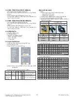
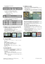
Summary of Contents for 32LV2510

Page 1: ...ETY PRECAUTIONS IN THIS MANUAL CHASSIS LB01U MODEL 32LV2510 32LV2530 TB MODEL 32LV2530 32LV2530 TD North Latin America http aic lgservice com Europe Africa http eic lgservice com Asia Oceania http biz lgservice com Internal Use Only Printed in Korea P NO MFL67002701 1101 REV00 ...

Page 2: ...right 2011 LG Electronics Inc All rights reserved Only for training and service purposes 2 CONTENTS CONTENTS 2 PRODUCT SAFETY 3 SPECIFICATION 6 ADJUSTMENT INSTRUCTION 9 BLOCK DIAGRAM 14 EXPLODED VIEW 15 SCHEMATIC CIRCUIT DIAGRAM ...

Page 3: ...Check Antenna Cold Check With the instrument AC plug removed from AC source connect an electrical jumper across the two AC plug prongs Place the AC switch in the on position connect one lead of ohm meter to the AC plug prongs tied together and touch other ohm meter lead in turn to each exposed metallic parts such as antenna terminals phone jacks etc If the exposed metallic part has a return path t...

Page 4: ... on your body by touching a known earth ground Alternatively obtain and wear a commercially available discharging wrist strap device which should be removed to prevent potential shock reasons prior to applying power to the unit under test 2 After removing an electrical assembly equipped with ES devices place the assembly on a conductive surface such as aluminum foil to prevent electrostatic charge...

Page 5: ... the solder joints of the two original leads If they are not shiny reheat them and if necessary apply additional solder Fuse and Conventional Resistor Removal Replacement 1 Clip each fuse or resistor lead at top of the circuit board hollow stake 2 Securely crimp the leads of replacement component around notch at stake top 3 Solder the connections CAUTION Maintain original spacing between the repla...

Page 6: ... prior to the adjustment 3 Test method 1 Performance LGE TV test method followed 2 Demanded other specification Safety CE IEC specification EMC CE IEC No Item Specification Remarks 1 Market Austrailia NewZealand Singapore Malaysia only Analog for A ASIA Vietnam Indonesia South Africa Israel A ASIA 2 Broadcasting system 1 PAL SECAM B G D K PAL for NZ SG 2 PAL I II 3 NTSC M 4 DVB T 3 Receiving syste...

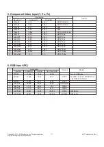
Page 7: ...1280x720 45 00 60 00 HDTV 720p 10 1920x1080 31 25 50 00 HDTV 1080i 11 1920x1080 33 75 60 00 HDTV 1080i 12 1920x1080 33 72 59 94 HDTV 1080i 13 1920x1080 56 250 50 HDTV 1080p 14 1920x1080 67 5 60 HDTV 1080p No Specification Proposed Remark Resolution H freq kHz V freq Hz Pixel Clock MHz 1 720 400 31 468 70 08 28 321 For only DOS mode 2 640 480 31 469 59 94 25 17 VESA Input 848 480 60 Hz 852 480 60 H...

Page 8: ...08 875 SXGA HDCP FHD model 7 1920 1080 67 5 60 00 138 625 WUXGA HDCP FHD model 2 PC Mode No Resolution H freq kHz V freq Hz Pixel clock MHz Proposed Remark 1 720 480 31 469 31 5 59 94 60 27 00 27 03 SDTV 480P 2 720 576 31 25 50 54 SDTV 576P 3 1280 720 37 500 50 74 25 HDTV 720P 4 1280 720 44 96 45 59 94 60 74 17 74 25 HDTV 720P 5 1920 1080 33 72 33 75 59 94 60 74 17 74 25 HDTV 1080I 6 1920 1080 28 ...

Page 9: ... check OK message If Error is displayed Check connection between computer jig and set 3 Click Read tab and then load download file XXXX bin by clicking Read 4 Click Connect tab If Can t is displayed check connection between computer jig and set 5 Click Auto tab and set as below 6 Click Run 7 After downloading check OK message USB DOWNLOAD 1 Put the USB Stick to the USB socket 2 Automatically detec...

Page 10: ... 00 60 RGB Input 1024 768 ad 00 10 Adjust 1024 768 RGB aa 00 90 End Adjust mode Required equipment Adjustment R C 3 2 Function Check Check display and sound Check Input and Signal items cf work instructions 1 TV 2 AV SCART1 SCART2 CVBS 3 COMPONENT 480i 4 RGB PC 1024 x 768 60hz 5 HDMI 6 PC Audio In Display and Sound check is executed by Remote control 10 LGE Internal Use Only Copyright 2011 LG Elec...

Page 11: ... Balance by pushing G key at 6 White Balance After you finished all adjustments Press In start key and compare Tool option and Area option value with its BOM if it is correctly same then unplug the AC cable If it is not same then correct it same with BOM and unplug AC cable For correct it to the model s module from factory Jig model Push the IN STOP key after completing the function inspection And...

Page 12: ... Carry the command EDID data and Download A E 00 10 Automatically Download Model option The use of a internal pattern download EZ ADJUT 0 Tool Option1 1 Tool Option2 2 Tool Option3 3 Tool Option4 4 Country Group 5 ADC Calibration 6 White Balance 7 Test Pattern 8 EDID D L 9 Sub B C 10 V Com 11 P Gamma EDID D L HDMI1 HDMI2 HDMI3 RGB NG NG NG NG Reset Start EDID D L Reset Start HDMI1 HDMI2 HDMI3 RGB ...

Page 13: ...erial number D L must be conformed when it is produced in production line because serial number D L is mandatory by D book 4 0 Manual Download Model Name and Serial Number If the TV set is downloaded by OTA or Service man Sometimes model name or serial number is initialized Not always There is impossible to download by bar code scan so It need Manual download 1 Press the instart key of ADJ remote ...

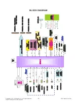
Page 14: ...ar TMDS DDR2 Add DDR2 Data SPI MICOM UPD78F0514AGA GAM AX MICOM SDA MICOM SCL AV Side NAND Flash 2Gbit HY27UF082G2B TPCB PCM_A 0 7 DDR3 256M Hynic H5TQ1G63BFR FFC 31P HD 50 60Hz TMDS HDMI CVBS L R DDR3 256M Hynic H5TQ1G63BFR DDR3 256M Hynic H5TQ1G63BFR CONTROL IR LED SOFT TOUCH NEC_EEPROM _SCL SDA LED_R BUZZ KEY1 KEY2 IR LED_B LG LOGO SOFT TOUCH _SCL SDA M24M01 HRMN6TP 1Mbit HDCP EEPROM CAT24WC08W...

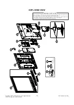
Page 15: ...ectrical and mechanical parts in this chassis have special safety related characteristics These parts are identified by in the Schematic Diagram and EXPLODED VIEW It is essential that these special safety parts should be replaced with the same components as recommended in this manual to prevent X RADIATION Shock Fire or other Hazards Do not modify the original design without permission of manufact...

Page 16: ...E24 C2M LLV2N BLUE 0 AF24 C3P LLV4P AF23 C3M LLV4N AD22 C4P LLV5P AE22 C4M LLV5N AF22 DCKP TCON5 AD19 DCKM TCON4 AE19 D0P LLV6P AD21 D0M LLV6N AE21 D1P LLV7P AF21 D1M LLV7N AD20 D2P LLV8P AE20 D2M LLV8N AF20 D3P TCON3 AF19 D3M TCON2 AD18 D4P TCON1 AE18 D4M TCON0 AF18 GPIO0 TCON15 HSYNC VDD_ODD AB22 GPIO1 TCON14 VSYNC VDD_EVEN AB23 GPIO2 TCON7 LDE GCLK4 AC23 GPIO3 TCON6 LCK GCLK2 AC22 FRC_GPIO0 UAR...

Page 17: ...D1 B_RX0N D2 B_RX1P E2 B_RX1N E3 B_RX2P F3 B_RX2N E1 DDCDB_DA GPIO26 D4 DDCDB_CK GPIO25 E4 HOTPLUGB GPIO20 D5 C_RXCP AA2 C_RXCN AA1 C_RX0P AB1 C_RX0N AA3 C_RX1P AB3 C_RX1N AB2 C_RX2P AC2 C_RX2N AC1 DDCDC_DA GPIO28 AB4 DDCDC_CK GPIO27 AA4 HOTPLUGC GPIO21 AC3 D_RXCP A2 D_RXCN A3 D_RX0P B3 D_RX0N A1 D_RX1P B1 D_RX1N B2 D_RX2P C2 D_RX2N C3 DDCDD_DA GPIO30 B4 DDCDD_CK GPIO29 C4 HOTPLUGD GPIO22 E5 CEC G...

Page 18: ...6 A0M RLV0N RED 8 U25 A1P RLV1P RED 7 U24 A1M RLV1N RED 6 V26 A2P RLV2P RED 5 V25 A2M RLV2N RED 4 V24 A3P RLV4P RED 1 W24 A3M RLV4N RED 0 Y26 A4P RLV5P GREEN 9 Y25 A4M RLV5N GREEN 8 Y24 BCKP TCON13 GREEN 1 AC26 BCKM TCON12 GREEN 0 AC25 B0P RLV6P GREEN 7 AA26 B0M RLV6N GREEN 6 AA25 B1P RLV7P GREEN 5 AA24 B1M RLV7N GREEN 4 AB26 B2P RLV8P GREEN 3 AB25 B2M RLV8N GREEN 2 AB24 B3P TCON11 BLUE 9 AC24 B3M...

Page 19: ... 24 25 C442 10uF 16V OPT R425 100 POWER_24_INV_CTL 0 R471 POWER_22_PWM_DIM C426 68uF 35V R402 100 C436 0 01uF 25V 0 01uF L406 3 6uH NR8040T3R6N R412 0 POWER_16_GND 12V 15V C424 0 1uF 16V R429 47K C485 0 1uF 16V IC402 AZ2940D 2 5TRE1 2 GND 3 VOUT 1 VIN R441 75K 1 8W 1 Q405 2SC3052 E B C R430 10K OPT 1 26V_VDDC C418 0 1uF 50V R435 22K L421 3 6uH NR8040T3R6N R423 10K 1 R418 6 8K OPT C447 0 1uF 16V IC...

Page 20: ...048 22 3 5V_ST R1019 22 R4035 4 7K NEW_SUB R4034 4 7K NEW_SUB C1008 15pF R1006 10K OPT R1011 10K TACT_KEY 3 5V_ST 3 5V_ST R1076 22 MICOM_DEBUG AMP_MUTE POWER_ON OFF1 LED_R BUZZ LED_B LG_LOGO C1006 0 1uF S7_NEC_TXD R1052 10K NEC_SCL R1018 22 R1074 10K GP3 MICOM_RESET FLMD0 R1047 20K 1 16W 1 R1041 22 R1056 22 R1037 22 NEC_ISP_Rx S T_SCL 3 5V_ST RL_ON NEC_EEPROM_SDA MICOM_RESET EDID_WP R1055 22 R1043...

Page 21: ... R2416 10K OPT R2405 10K 1 NEC_EEPROM_SCL D2402 5 6V AMOTECH R2411 100 EYEQ TOUCH_KEY IR C2401 0 1uF R2412 100 EYEQ TOUCH_KEY S T_SDA JP2409 C2406 1000pF 50V R2425 47K OPT 3 5V_ST Q2405 2SC3052 OPT E B C C2410 0 1uF 16V OPT C2405 0 1uF 16V C2407 100pF 50V L2403 BLM18PG121SN1D R2404 10K 1 R2430 10K OPT R2413 1 5K JP2408 C2404 1000pF 50V JP2411 D2401 5 6V AMOTECH 3 5V_ST 3 5V_ST L2402 BLM18PG121SN1D...

Page 22: ... USB1_OCD SIDE_USB_DP C1451 22uF 16V R1459 2K 1 8W 1 5V_USB USB1_CTL R1458 2K 1 8W 1 R1455 4 7K OPT SIDE_USB_DM L1451 MLB 201209 0120P N2 120 ohm R1454 10K 3 3V_Normal R1451 47 L1451 1 CIS21J121 JK1450 3AU04S 305 ZC LG USB_JACK 1 2 3 4 5 IC1450 AP2191DSG EAN61849601 3 IN_2 2 IN_1 4 EN 1 GND 5 FLG 6 OUT_1 7 OUT_2 8 NC JK1450 1 3AU04S 345 ZC H LG USB_JACK_LV3400 1 2 3 4 5 D1451 RCLAMP0502BA OPT 0 07...

Page 23: ... DDC_SCL_2 BSS83 Q805 S B D G CEC_REMOTE_NEC DDC_SCL_4 GND HDMI_CEC CK _HDMI4 JP806 R854 68K R875 22 R835 3 3K HPD1 HPD4 D0 _HDMI1 R878 22 HDMI_CEC D0 _HDMI2 R804 1 8K R897 1K C810 0 1uF 16V C801 0 1uF 16V D0 _HDMI4 D803 AVRL161A1R1NT OPT 5V_HDMI_1 BSS83 Q806 S B D G R876 22 C805 0 1uF 16V DDC_SDA_1 R893 10K IC804 AT24C02BN SH T HDMI_SIDE_ATMEL 3 A2 2 A1 4 GND 1 A0 5 SDA 6 SCL 7 WP 8 VCC JK801 EAG...

Page 24: ...N_GND 8 BLUE_GND 9 NC 10 SYNC_GND 11 GND_2 12 DDC_DATA 13 H_SYNC 14 V_SYNC 15 DDC_CLOCK 16 SHILED R1107 15K JK1103 JST1223 001 1 GND 2 VCC 3 VINPUT 4 FIX_POLE 3 3V_Normal R1135 75 R1155 1K HP_LOUT 002 V7 C1126 68pF 50V OPT C1119 10uF 16V SPDIF_OUT 002 T18 D1109 30V C1129 0 1uF 16V PC_R_IN 002 S12 R1129 3 3K R1137 75 3 3V_Normal D1101 5 6V OPT AMOTECH EDID_WP R1147 1K SIDE_HP_MUTE IC1105 AT24C02BN ...

Page 25: ...1101 SPG09 DB 009 1 2 3 4 5 6 7 8 9 10 JP1121 IC1101 MAX3232CDR EAN41348201 3 C1 2 V 4 C2 1 C1 6 V 5 C2 7 DOUT2 8 RIN2 9 ROUT2 10 DIN2 11 DIN1 12 ROUT1 13 RIN1 14 DOUT1 15 GND 16 VCC S7_NEC_TXD D1108 30V CDS3C30GTH OPT C1102 0 1uF JP1122 C1106 0 1uF S7_NEC_RXD C1103 0 1uF C1101 0 33uF C1104 0 1uF 3 5V_ST D1107 30V CDS3C30GTH OPT R1123 100 C1105 0 1uF RS232C 20101023 GP2R RS232C_9PIN 10 Copyright 2...

Page 26: ..._DIM C700 10uF 16V OPT RXD1 RXA0 RXC1 R710 10K OPT PWM_DIM RXBCK C710 0 1uF 16V WAFER_FHD SCAN_BLK1 OPC_OUT RXA2 RXB2 RXD2 P705 FF10001 30 HD 1 2 3 4 5 6 7 8 9 10 11 12 13 14 15 16 17 18 19 20 21 22 23 24 25 26 27 28 29 30 31 RXD1 P703 FI RE51S HF J R1500 WAFER_FHD 1 2 3 4 5 6 7 8 9 10 11 12 13 14 15 16 17 18 19 20 21 22 23 24 25 26 27 28 29 30 31 32 33 34 35 36 37 38 39 40 41 42 43 44 45 46 47 48...

Page 27: ..._DQU5 DDR2_DQ12 K26 B_DDR3_DQU6 DDR2_DQM0 G25 B_DDR3_DQU7 DDR2_DQ14 K24 H5TQ1G63DFR H9C IC1202 DDR_1333_HYNIX EAN61828901 A0 N3 A1 P7 A2 P3 A3 N2 A4 P8 A5 P2 A6 R8 A7 R2 A8 T8 A9 R3 A10 AP L7 A11 R7 A12 BC N7 A13 T3 NC_5 M7 BA0 M2 BA1 N8 BA2 M3 CK J7 CK K7 CKE K9 CS L2 ODT K1 RAS J3 CAS K3 WE L3 RESET T2 DQSL F3 DQSL G3 DQSU C7 DQSU B7 DML E7 DMU D3 DQL0 E3 DQL1 F7 DQL2 F2 DQL3 F8 DQL4 H3 DQL5 H8 ...

Page 28: ...ormal IC1401 1 W25Q80BVSSIG S_FLASH_MAIN_WINBOND 3 WP IO2 2 DO IO1 4 GND 1 CS 5 DI IO0 6 CLK 7 HOLD IO3 8 VCC R1401 0 OPT FLASH_WP SPI_SDI R1405 33 SPI_SDO SPI_SCK SPI_CS 3 3V_Normal 3 3V_Normal R1404 4 7K R1403 10K Q1401 KRC103S OPT E B C C1401 0 1uF IC1401 MX25L8006EM2I 12G S_FLASH_MAIN_MACRONIX 3 WP 2 SO SIO1 4 GND 1 CS 5 SI SIO0 6 SCLK 7 HOLD 8 VCC SFLASH_1MB 20101023 13 GP2R Copyright 2011 LG...

Page 29: ...U3702 3 UDA55AL GP3_ATSC_1INPUT_H_SANYO 14 3 3V 13 1 2V 5 AS 12 GND 11 VIDEO 2 NC_2 10 NC_3 4 NC RF_AGC 1 NC_1 17 DIF_1 9 SIF 8 NC IF_TP 3 B 5V 16 IF_AGC_CNTL 7 SDA 6 SCL 15 RESET 18 DIF_2 19 SHIELD TU3701 2 TDFR B036F FULL_NIM_BR 1 RF_S W_CNTL 2 BST_CNTL 3 B1 5V 4 NC_1 RF_AGC 5 NC_2 6 SCLT 7 SDAT 8 NC_3 9 SIF 10 NC_4 11 VIDEO 12 GND 13 B2 1 2V 14 B3 3 3V 15 RESET 16 NC_5 17 SCL 18 SDA 19 ERR 20 S...

Page 30: ...F C539 50V 0 1uF C509 C528 10uF 35V R520 12 0 1uF C526 50V C511 10uF 10V OPT C545 22pF 50V OPT C434 0 1uF 16V 0 1uF C538 50V SPK_L R503 100 C531 390pF 50V 1 8V_AMP R514 100 C522 1uF 25V 0 1uF C527 50V POWER_DET C525 22000pF 50V Q501 2SC3052 E B C D501 100V 1N4148W OPT C503 10uF 10V OPT AUD_LRCH R508 3 3K C530 390pF 50V C534 0 47uF 50V 1 8V_AMP SPK_R C546 22pF 50V OPT C517 1uF 25V L502 BLM18PG121SN...

Page 31: ...70K REAR_AV R1664 33K EU_OPT C1618 4700pF EU_OPT R1668 10K EU_OPT SC1 COMP1_DET C1644 10uF 16V EU_OPT R4221 0 EU_OPT C1662 330pF 50V REAR_AV AV_L_IN D1607 5 6V NON_EU C1612 330pF 50V DTV MNT_L_OUT D1601 5 6V OPT COMP2_Pb D1716 30V OPT D1602 30V OPT 12V 15V C1621 47uF 16V EU_OPT 0 R4210 EU_OPT C1620 100uF 16V EU_OPT DTV MNT_R_OUT SC_RE1 R1685 10K REAR_AV AV_CVBS_DET REC_8 R1626 470K C1664 0 01uF 2S...

Page 32: ... WH O SPRING 3C RD CONTACT 4C RD O SPRING 5C RD E LUG D9906 30V SIDE_COMP R9914 10K SIDE_CVBS C9906 100pF 50V SIDE_CVBS SIDEAV_R_IN R9906 470K SIDE_CVBS D9908 5 6V OPT R9905 470K SIDE_CVBS R9912 1K SIDE_COMP L9902 BLM18PG121SN1D SIDE_CVBS C9905 100pF 50V SIDE_CVBS R9916 12K SIDE_CVBS SIDEAV_L_IN JK9901 KJA PH 1 0177 SIDE_AV_GENDER 3 M3_DETECT 4 M4 5 M5_GND 1 M1 6 M6 SIDEAV_DET R9909 75 SIDE_COMP L...

Page 33: ... L1902 BLM18PG121SN1D R1901 47 CI_MDI 6 CI_MDI 2 PCM_WAIT CI_ADDR 4 C1903 0 1uF 16V CI_TS_DATA 5 PCM_IOWR PCM_A 12 R1924 10K CI_TS_DATA 1 CI_ADDR 12 R1923 10K OPT GND AR1906 33 PCM_A 11 CI_CD1 PCM_OE CI_IORD R1913 10K CI_IOWR AR1909 33 CI_MISTRT R1915 47 R1917 10K 3 3V_CI 5V_Normal 5V_Normal CI_MDI 6 CI_ADDR 9 AR1907 33 R1912 10K OPT PCM_A 1 PCM_A 7 PCM_IRQA AR1904 33 R1908 100 R1906 10K CI_MCLKI ...

Page 34: ... MDS62110205 GAS3 2 7 5T_GAS MDS61887708 GAS2 4 12 5T_GAS MDS62110204 GAS1 1 5 5T_GAS MDS62110204 GAS2 1 5 5T_GAS MDS61887710 GAS2 3 9 5T_GAS MDS61887710 GAS5 3 9 5T_GAS MDS61887708 GAS5 4 12 5T_GAS MDS62110206 GAS5 6 5T_GAS MDS62110205 GAS5 2 7 5T_GAS MDS62110204 GAS5 1 5 5T_GAS MDS62110209 GAS1 5 8 5T_GAS MDS62110209 GAS2 5 8 5T_GAS MDS62110209 GAS3 5 8 5T_GAS MDS62110209 GAS4 5 8 5T_GAS MDS6211...

Page 35: ...8pF 50V OPT R2100 2 2K LED_DRIVER_D L C2102 18pF 50V OPT C2100 18pF 50V OPT V_SYNC L DIM_MOSI C2104 18pF 50V OPT C2101 18pF 50V OPT R2101 2 2K LED_DRIVER_D L LED_DRIVER_D L_SDA P2100 12507WR 08L L DIM_LED DRIVER 1 2 3 4 5 6 7 8 9 3 3V_Normal LED_DRIVER_D L_SCL 3 3V_Normal R2103 10K FRC_L DIM_REVERSE_SEL R2102 10K OPT R4029 22 LED_DRIVER_D L R4028 22 LED_DRIVER_D L L DIM_LED 20101023 21 GP2R Copyri...

Page 36: ...06 22 3D_SG M_REMOTE_RX R3405 22 3D_SG R3402 100 3D_SG R3408 100 3D_SG L3401 120 ohm 3D_SG R3411 2 7K 3D_SG 3 3V_Normal R3410 2 7K 3D_SG R3412 2 7K 3D_SG DD_MREMOTE M_RFModule_RESET R3403 22 3D_SG 3 3V_Normal M_REMOTE_TX R3401 100 3D_SG 3D_GPIO_2 3D_GPIO_1 R3404 22 3D_SG R3409 100 3D_SG DC_MREMOTE R3407 100 3D_SG 1 1 1 0 0 1 RESERVED GPOIO_0 0 ALL 3D SG OPTION 1 RESERVED 1 GPOIO_2 3D Off 50Hz FREQ...

Page 37: ......

Page 38: ...B Power error No power 6 7 Off when on off while viewing power auto on off 7 8 C Audio error No audio Normal video 8 9 Wrecked audio discontinuation noise 9 10 D Function error No response in remote controller key error recording error memory error 10 11 External device recognition error 11 12 E Noise Circuit noise mechanical noise 12 13 F Exterior error Exterior defect 13 1 Trouble Shooting Copyr...

Page 39: ... End Always check record S W Version and White Balance value before replacing the Main Board Replace Main Board Re enter White Balance value Precaution Established date Standard Repair Process Revised date 1 13 LCD TV Error symptom A Video error No video Normal audio A4 A1 A2 A28 A7 A3 First of all Check whether all of cables between board is inserted properly or not Main B D Power B D LVDS Cable ...

Page 40: ... and replace MAIN B D Y Replace Power Board and repair parts N End Standard Repair Process A Video error No video No audio A4 Established date Revised date 2 13 LCD TV Error symptom 2 Copyright 2011 LG Electronics Inc All rights reserved Only for training and service purposes LGE Internal Use Only ...

Page 41: ...eck Tuner soldering Normal Picture Y N Y Close Close By using Digital signal level meter By using Diagnostics menu on OSD Menu Setup Manual Tuning Signal strength Normal over 30 Signal Quality Normal over 30 Normal Picture Y Contact with signal distributor or broadcaster Cable or Air N Normal Picture Y Close N Standard Repair Process Established date Revised date 3 13 LCD TV Error symptom 3 N Norm...

Page 42: ...external device and cable Y External device Cable normal RGB HDMI DVI error Check external device and cable Replace Main B D Replace Main B D N N A Video error Color error N Y End Replace module Request repair for external device cable Color error Check Test pattern Standard Repair Process Established date Revised date 4 13 LCD TV Error symptom 4 Copyright 2011 LG Electronics Inc All rights reserv...

Page 43: ... and HDMI DVI by connecting Jig pattern Generator Set top Box etc N Y Replace Main B D Screen normal Check screen condition by input External Input Component RGB HDMI DVI Request repair for external device Component error RGB error HDMI DVI Connect other external device and cable Check normal operation of External Input Component RGB and HDMI DVI by connecting Jig pattern Generator Set top Box etc...

Page 44: ...e of each output of Power B D N Y Normal voltage Replace Main B D N Y OK Replace Main B D N Y Normal Check ST BY 3 5V Replace Power B D N Y Normal voltage Replace Power B D Y A17 A18 A19 A4 Standard Repair Process Established date Revised date 6 13 LCD TV Error symptom 6 Stand By Red Operating white Close Copyright 2011 LG Electronics Inc All rights reserved Only for training and service purposes ...

Page 45: ...EY Power off by REMOTE CONTROL POWEROFF_OFFTIMER Power off by OFF TIMER POWEROFF_SLEEPTIMER Power off by SLEEP TIMER POWEROFF_INSTOP Power off by INSTOP KEY POWEROFF_AUTOOFF Power off by AUTO OFF POWEROFF_ONTIMER Power off by ON TIMER POWEROFF_RS232C Power off by RS232C POWEROFF_RESREC Power off by Reservated Record POWEROFF_RECEND Power off by End of Recording POWEROFF_SWDOWN Power off by S W Dow...

Page 46: ...ard and repair parts Check Speaker disconnection N Y Replace Speaker Replace MAIN Board End C Audio error No audio Normal video A24 A25 Disconnection Established date Revised date 8 13 LCD TV Error symptom Standard Repair Process 8 Copyright 2011 LG Electronics Inc All rights reserved Only for training and service purposes LGE Internal Use Only ...

Page 47: ...ect and check other external device N Y Normal audio Check and fix external device Replace Power B D N Y Normal voltage Check input signal RF External Input signal Signal normal When RF signal is not received Request repair to external cable ANT provider Y Check audio B Voltage 20V or 24V Replace Main B D In case of External Input signal error Check and fix external device Replace Main B D N End E...

Page 48: ...place Baterry of R C Check Repair Cable connection Connector solder Normal operating Check 3 5V On Main B D A27 Normal Voltage Close N N Check 3 5v on Power B D Replace Power B D or Replace Main B D Power B D don t have problem A4 Check IR Output signal Normal Signal N Y Repair Replace IR B D N A27 Replace Main B D Y A27 Standard Repair Process Established date Revised date 10 13 LCD TV Error symp...

Page 49: ...rnal device cable RGB HDMI DVI Optical Recognition error Replace Main B D Replace Main B D Fix in accordance with technical information D Function error External device recognition error Established date Revised date 11 13 LCD TV Error symptom Standard Repair Process 11 Copyright 2011 LG Electronics Inc All rights reserved Only for training and service purposes LGE Internal Use Only ...

Page 50: ...ceed as shown in the solution manual For models without any fix information provide the description OR Mechanical noise is a natural phenomenon and apply the 1st level description When the customer does not agree apply the process by stage Describe the basis of the description in Part related to nose in the Owner s Manual E Noise Circuit noise mechanical noise Established date Revised date 12 13 L...

Page 51: ...remote controller Remote controller damage Stand dent Replace stand F Exterior defect Exterior defect Established date Revised date 13 13 LCD TV Error symptom Standard Repair Process 13 Copyright 2011 LG Electronics Inc All rights reserved Only for training and service purposes LGE Internal Use Only ...

Page 52: ...tc Standard Repair Process Detail Technical Manual TUNER input signal strength checking method A Video error_Video error video lag stop ALL MODELS A6 Established date Revised date Error symptom Content LCD TV A6 Copyright 2011 LG Electronics Inc All rights reserved Only for training and service purposes LGE Internal Use Only ...

Page 53: ...top 1 Checking method for remote controller for adjustment Press the IN START with the remote controller for adjustment Version ALL MODELS A7 Established date Revised date Error symptom Content LCD TV A7 Copyright 2011 LG Electronics Inc All rights reserved Only for training and service purposes LGE Internal Use Only ...

Page 54: ...ection diagram 1 A Video error _Vertical Horizontal bar residual image light spot A8 Established date Revised date Error symptom Content LCD TV A8 Copyright 2011 LG Electronics Inc All rights reserved Only for training and service purposes LGE Internal Use Only ...

Page 55: ...erns using the ADJ Key Checking item 1 Defective pixel 2 Residual image 3 MODULE error ADD BAR SCAN BAR 4 Video error Classification of MODULE or Main B D A12 Established date Revised date Error symptom Content LCD TV A12 Copyright 2011 LG Electronics Inc All rights reserved Only for training and service purposes LGE Internal Use Only ...

Page 56: ...older defect CNT Broken Solder defect CNT Broken Solder defect CNT Broken Abnormal Power Section Solder defect Short Crack Abnormal Power Section Solder defect Short Crack Appendix Exchange T Con Board 1 A 1 5 Copyright 2011 LG Electronics Inc All rights reserved Only for training and service purposes LGE Internal Use Only ...

Page 57: ...r Section Solder defect Short Crack Fuse Open Abnormal power section Noise GRADATION GRADATION Abnormal Display Appendix Exchange T Con Board 2 A 2 5 Copyright 2011 LG Electronics Inc All rights reserved Only for training and service purposes LGE Internal Use Only ...

Page 58: ...dix Exchange PSU LED driver No Light Dim Light Dim Light Dim Light No picture Sound Ok A 3 5 Copyright 2011 LG Electronics Inc All rights reserved Only for training and service purposes LGE Internal Use Only ...

Page 59: ...ss damage Crosstalk Crosstalk Press damage Panel Mura Light leakage Press damage A 4 5 Un repairable Cases In this case please exchange the module Copyright 2011 LG Electronics Inc All rights reserved Only for training and service purposes LGE Internal Use Only ...

Page 60: ...k Source TAB IC Defect Horizontal Block Gate TAB IC Defect Horizontal line Gate TAB IC Defect Gate TAB IC Defect Horizontal Block Gate TAB IC Defect Appendix Exchange the Module 2 A 5 5 Un repairable Cases In this case please exchange the module Copyright 2011 LG Electronics Inc All rights reserved Only for training and service purposes LGE Internal Use Only ...

Page 61: ... 3 Standard Repair Process Detail Technical Manual POWER OFF MODE checking method B Power error _Off when on off whiling viewing ALL MODELS A22 Established date Revised date Error symptom Content LCD TV A22 Copyright 2011 LG Electronics Inc All rights reserved Only for training and service purposes LGE Internal Use Only ...

Page 62: ...ff to On Standard Repair Process Detail Technical Manual Checking method in menu when there is no audio C Audio error_No audio Normal video ALL MODELS A24 Established date Revised date Error symptom Content LCD TV A24 Copyright 2011 LG Electronics Inc All rights reserved Only for training and service purposes LGE Internal Use Only ...

Reviews: