background image

- 8 -

Copyright © 

 LG Electronics Inc. All rights reserved.

Only training and service purposes.

 Insert HDMI Jack which is connected with PC for White Bal-

ance or equivalent device.

  Total Assembly line should check whether the color 

coordinate(x,y) data refer to below table were meet or not.

*Note :  x,y coordinates are drifted about 0.007 after 30 mins 

heat-run. So checking color coordinate within 5-min at 

total assembly line, consider x,y coordinates might be 

up to 0.007 than x,y target of each color temperature. 

* Note : Manual W/B process 

1)  Power of

f => Power on (‘←

 3 times, ‘→

’ 1 time and push ‘

’)

2) and push the “←” or “→”.

3) In Service Menu.

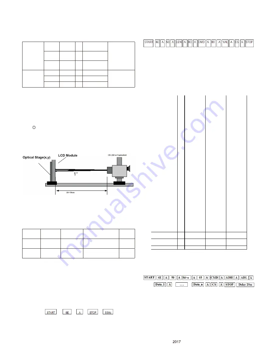
*  When doing Adjustment, Please make circumstance as 

below.

4.3. DPM Operation check

■ Measurement Condition: 100 ~ 240 V @ 50/60Hz

(1) Set Input to DVI-D, DisplayPort, HDMI1, HDMI2

(2) Turn off the source device.

(3) Check DPM operation refer to the below table.

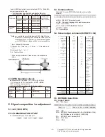
5. Signal composition for adjustment

5.1. I2C (100K BPS)
5.2. COMMUNICATION START

# Until ACK BIT goes LOW, Repeat it.

5.3. Command form.

Command form use DDC2AB standard communication 

protocol.

a. LEN  : DATA BYTE number to send.

b. CMD : Command language that monitor executes.

c. 

V

AL :  FOS DATA

d. CS  : Dada’s CHECHSUM that transmit

e. DELAY : 50MS           

f. A : Acknowledge    

5.4. Screen adjust command (LENGTH = 84)


5.5. EEPROM Data Write

5.5.1 Siganl TABLE

LEN  :  84h+Bytes

CMD  :  E8h

ADH  :  E2PROM  Slave 

Address(A0,A2,A4,A6,A8,AA,AC,AE), 

Not 00h(Reserved by Buffer To EEPROM)

ADL  :  E2PROM  Sub 

Address(00~FF)

Data  :  Write data

Delay :   20ms

Color 

Temperature

Cool

9,300

°K

X=0.283 (±0.03)

Y=0.298 (±0.03)

<Test Signal>

Inner pattern

(255gray,80IRE)

Medium

8,000

°K

X=0.295 (±0.03)

Y=0.305 (±0.03)

Warm

6,500

°K

X=0.313 (±0.03)

Y=0.329 (±0.03)

Luminance

(cd/m²)

Cool

Min : 170

<Test Signal>

Inner pattern

(255gray,80IRE)

Medium

Min : 200

Warm

Min : 

260

Operating 

Condition

Sync (H/V) 

or 

V

ideo

EUT

(MSPG6100)

LED

(SET)

Wattage

(W)

Sleep 

mode

Off/Off

Off

White blinking

1.2W

Off 

mode

-

-

Off

0.3

No.

Adjustment contents CMD(h

ex)

ADR

VA

L(hex)

Explanation

1

EEPROM ALL INITIA

L

E

4

00

00

adjustment Initiali

z

ation

2

EEPROM READ

E7

Slave add

At EEPROM  Read 

3

EEPROM WRITE

E8

Slave add

Data

Write data at EEPROM

4

R GAIN

1

6

00

00-

64

Tune Gain

5

G GAIN

18

00

00-

64

6

B GAIN

00

00-

64

7

BRIGHT(Backlight)

10

00

00-

64

Tune Analog Bright

8

FACTORY RESET

F0

00

0

Factory reset

9

AUTO_COLOR_ADJ

UST

F1

00

0

AUTO COLOR Tuning

0:Auto color

10

COLOR_MODE_CH

ANGE

F2

00

1

WARM(

6500

K)

2

COOL(9300K)

11

Elapsed time Clear

E9

00

00

Aging off  &Clear elapse

d time

12

Aging On/Off

F3

00

FF/00

FF:ON / 00:OFF

13

Input Select

F

4

00

0xD0

1:DisplayPort

0x90

2:HDMI1

0x91

3:HDMI2

0xD1

4

:Thunderbolt (UC98 o

nly)

1

4

SYSTEM  RESET

F5

00

00

RestartSystem

15

Select Language

6

8

00

0x00 

~

 0x0F

00:English,
01:German
02:French
03:Spanish
0

4

:Italian

05:Swedish,
0

6

:Finnish

07:Portuguese
08:Bra

z

il

09:Polish
0A:Russian
0B:Greek
0C:Ukrainian
0D:Chinese
0E:Japanese
0F:Korean

EDID SN UPDATE

0x77

0

0x01

~

0x02

0x01 :HDMI1
0x02 :HDMI2

APD command

0xF7

00

0x00

~

0x01

0x00:OFF
0x01:ON

Module name

LM

34

0UW3

Summary of Contents for 34UC80

Page 1: ...E CHASSIS READ THE SAFETY PRECAUTIONS IN THIS MANUAL SERVICE MANUAL Copyright 2017 LG Electronics Inc All rights reserved Only training and service purposes P NO MFL70211501 1708 REV00 LED MONITOR SERVICE MANUAL CONFIDENTIAL LM55E 34UC80 34UC80 BF ...

Page 2: ...s Inc All rights reserved Only training and service purposes BLOCK DIAGRAM 10 1 1 W E I V D E D O L P X E DISASSEMBLY 12 TROUBLE SHOOTING GUIDE 14 CONTENTS 2 SAFETY PRECAUTIONS 3 SPECIFICATION 4 ADJUSTMENT INSTRUCTION 6 CONTENTS ...

Page 3: ...l shock Leakage Current Cold Check Antenna Cold Check With the instrument AC plug removed from AC source connect an electrical jumper across the two AC plug prongs Place the AC switch in the on position connect one lead of ohm meter to the AC plug prongs tied together and touch other ohm meter lead in turn to each exposed metallic parts such as antenna terminals phone jacks etc If the exposed meta...

Page 4: ...s Name LM55E 6 General Scope External SW Adj 5 way joystick switch Function PBP Picture Mode Ratio Gamma Calibration SES Six Color 7W speaker x 2 DisplayPort HDMI x 2 Screen split USB hub USB3 0 x 2 7 Input HDMI1 2 IN HDMI 1 and HDMI 2 DP IN Display Port Thunderbolt N A USB UP USB upstream only with Host PC USB 1 2 USB downstream only with Host PC Quick Charge USB 1 only H P Audio L R 8 Power Code...

Page 5: ... 5 H Pixels 74 25 45 1650 1280 110 40 220 1280x720 HDMI V Lines 60 750 720 5 5 20 DP 6 H Pixels 108 63 981 1688 1280 48 112 248 1280x1024 HDMI V Lines 60 02 1066 1024 1 3 38 DP 7 H Pixels 108 60 1800 1600 24 80 96 1600 x 900 HDMI V Lines 60 1000 900 1 3 96 DP 8 H Pixels 146 25 65 29 2240 1680 104 176 280 1680x1050 HDMI V Lines 59 954 1089 1050 3 6 30 DP 9 H Pixels 148 5 67 5 2200 1920 88 44 148 19...

Page 6: ... 110 DDC Adjustment Jig equipment 3 Main PCB check process APC After Manual Insult executing APC 3 1 ADC Process N A 3 2 EDID Process 3 2 1 EDID Download F W includes default EDID for All input ports aging on Mode If AC ON default EDID is automatically loaded to EEPROM Update serial number in EDID of HDMI1 Caution Never connect HDMI Cable when execute HDMI EDID automatically Protocol DDC 2AB EDID ...

Page 7: ...OM by using DDC2AB protocol HDCP Adjustment Jig equipment If error is occurred try to write again After download HDCP key send command 0xE6 00 00 for loading RAM memory correctly 4 2 White balance adjustment Adjust PRESET Warm 6500K Color coordinates and Gamma calibration Set the CA 210 for calibration Input Gamma calibration Pattern R G B Grey 20 Set as Warm 6500K by commanding COLOR_MODE_ CHANGE...

Page 8: ... 00h Reserved by Buffer To EEPROM ADL E2PROM Sub Address 00 FF Data Write data Delay 20ms Color Temperature Cool 9 300 K X 0 283 0 03 Y 0 298 0 03 Test Signal Inner pattern 255gray 80IRE Medium 8 000 K X 0 295 0 03 Y 0 305 0 03 Warm 6 500 K X 0 313 0 03 Y 0 329 0 03 Luminance cd m Cool Min 170 Test Signal Inner pattern 255gray 80IRE Medium Min 200 Warm Min 260 Operating Condition Sync H V or Video...

Page 9: ...7F D data 8 byte write L 0x00 0x10 0x70 5 6 5 EDID Read DDC2B Command A0 A1 128 Byte transfer of EDID Buffer of MICOM No Adjustment contents CMD hex LEN Explanation 1 E E P R O M WRITE E8 94 16 Byte Write 2 84 n n byte Write No Adjustment contents CMD hex ADH hex ADL hex Explanation 1 EEPROM READ E7 A0 0 0 Page 0 7F Read 2 80 0 Page 80 FF Read 3 A2 0 1 Page 0 7F Read 4 80 1 Page 80 FF Read 5 A4 0 ...

Page 10: ... 10 Copyright LG Electronics Inc All rights reserved Only training and service purposes BLOCK DIAGRAM ...

Page 11: ...lated characteristics These parts are identified by in the EXPLODED VIEW It is essential that these special safety parts should be replaced with the same components as recommended in this manual to prevent Shock Fire or other Hazards Do not modify the original design without permission of manufacturer IMPORTANT SAFETY NOTICE 910 900 920 510 300 200 100 500 330 400 LV1 540 ...

Page 12: ...Preparation tool jig 1 2 Tool Curved Packing in a box 2 Stand Assembly Separation 1 Put a product on a curved packing 2 Pull a button and disassemble a stand a e 4 s w e r c s e v o m e r r e v i r D w e r c s a g n i s U 3 3 Back cover Assembly r e v o c k c a b a e l b m e s s a s i d g i j c i t s a l p g n i s U 1 ...

Page 13: ...ed Only training and service purposes and Tapes s e l b a C e l b m e s s a s i d n o i t a r a p e s r e v o C k c a B r e t f A 2 3 Disassemble Control PCB Ass y Latch Type 34UC88 80 model is common structure 4 Disassemble screws 10ea Module Cabinet ...

Page 14: ...Power Replace X200 N Check C410 Voltage Level 19V Check Power connector OK Replace Adapter Y N Y Check IC400 Output Voltage Level 3 3V Replace IC400 Recheck Y N Check X200 Clock 12MHz Check IC401 Output Voltage Level 5V Replace IC401 Recheck N Y Replace IC202 Flash Memory Y Check IC403 Output Voltage Level 1 15V 1 8 Replace IC403 Recheck N Y ...

Page 15: ...0 IC701 Replace LED Driver IC Y N N Check Panel Power 10V L408 Check IC402 Output 10V Replace IC402 Recheck Y N Check Panel eDP AUX P101 17 18 Check IC200 Repair Scaler Y N Check eDP FFC Cable for Damage or Open Conductors Check LED Driver Output IC700 IC701 1 2 5 6 PIN Replace T Con Board or Module Y Check IC204 Replace Main Scaler IC N Check WLED_ENABLE High IC700 IC701 3 PIN Y ...

Page 16: ...for training and service purposes 3 No Video HDMI Replace Main Scaler Check input signal format Is it supported Check JK100 JK101 for proper connection or Damage Replace Connector Y N Check I2C Signal EDID Re Download EDID Data Y N Y Check HDMI Cable for Damage or Open Connector Y ...

Page 17: ...Inc All rights reserved Only for training and service purposes 4 No Video DP Replace Main Scaler Check input signal format Is it supported Check JK102 for proper connection or Damage Replace Connector Y N Y Check DP Cable for Damage or Open Connector Y ...

Page 18: ......

Reviews: