background image

- 31 -

120

6400WMCX03A

SPEAKER, WOOFER G1560102 MACOM WOOFER 8OHM 15/20W 82DB OTHERS 100HZ 193*57MM

121

6400DTTX02B

SPEAKER, TWEETER EN15D-6659 TOPTONE TWEETER(DOME) 8OHM 15/20W 78DB OTHERS PC1 MODEL

200

6348Q-E113H

PDP, 42” 852*480 PDP42V80201.AKLGG  42PC1RV-ZJ CIS  SET

6348Q-E127T

PDP, 42 852*480 PDP42V80201.ADLGB

201

6871QCH074A

PWB(PCB) ASSEMBLY, DISPLAY CTRL ASSY HAND INSERT 42 42V8 4005 ASIC LVDS

202

6871QDH118A

PWB(PCB) ASSEMBLY, DISPLAY YDRV ASSY HAND INSERT 42 42V8 80PIN SCAN IC APLICATION

203

6871QLH057A

PWB(PCB) ASSEMBLY, DISPLAY XRLT ASSY HAND INSERT 42 42V8 XL 4004 ASIC LVDS

204

6871QRH067A

PWB(PCB) ASSEMBLY, DISPLAY XRRT ASSY HAND INSERT 42 42V8  XR 4004 ASIC LVDS

205

6871QYH048A

PWB(PCB) ASSEMBLY, DISPLAY YSUS ASSY HAND INSERT 42 42V8 Y SUS B/D

206

6871QZH053A

PWB(PCB) ASSEMBLY, DISPLAY ZSUS ASSY HAND INSERT 42 42V8

240

4980900109A

SUPPORTER, ASSY AL 42PC1R-TA, VERTICAL RIGHT  42PC1RV-ZJ CIS  SET

4980900109C

SUPPORTER, ASSY AL 42PC1R-TA, VERTICAL RIGHT, C/SKD

250

4980900109B

SUPPORTER, ASSY AL 42PC1R-TA, VERTICAL LEFT  42PC1RV-ZJ CIS  SET

4980900109D

SUPPORTER, ASSY AL 42PC1R-TA, VERTICAL LEFT, C/SKD

300

30919E0006A

CABINET ASSEMBLY, 42PC1RV-ZJ BRAND 30909E0001A  42PC1RV-ZJ CIS  SET

30919E0006C

CABINET ASSEMBLY, 42PC1RV-TJ(CHINA) BRAND 30909E0001A->  42PC1RVA-ZJ

30919E0006H

CABINET ASSEMBLY, 42PC1RV-ZJ BRAND 30909E0001A C/SKD ->  42PC1RV-ZJ

301

4980900113A

SUPPORTER, ASSY AL FILTER TOP 42PC1R-TA  42PC1RV-ZJ CIS  SET

4980900113B

SUPPORTER, ASSY AL FILTER TOP 42PC1R-TA C/SKD

302

4980900114A

SUPPORTER, ASSY AL FILTER BOTTOM 42PC1R-TA  42PC1RV-ZJ CIS  SET

4980900114B

SUPPORTER, ASSY AL FILTER BOTTOM 42PC1R-TA C/SKD

303

4980900115A

SUPPORTER, ASSY AL FILTER RIGHT 42PC1R-TA  42PC1RV-ZJ CIS  SET

4980900115B

SUPPORTER, ASSY AL FILTER RIGHT 42PC1R-TA, C/SKD

304

4980900116A

SUPPORTER, ASSY AL FILTER LEFT 42PC1-TA  42PC1RV-ZJ CIS  SET

4980900116B

SUPPORTER, ASSY AL FILTER LEFT 42PC1-TA, C/SKD

400

3809900103A

BACK COVER ASSEMBLY, 42PC1R ANALOG  42PC1RV-ZJ CIS  SET

3809900103P

BACK COVER ASSEMBLY, 42PC1 LGEMA ASSY ONLY (ANALOG)

430

3501900014A

BOARD ASSEMBLY, D/T SPK STAND AP-42DC11 MF056A FOLDING STAND  42PC1RV-ZJ CIS  SET

3501900014C

BOARD ASSEMBLY, D/T SPK STAND AP-42DC11 MF056A FOLDING STAND LGERS C/SKD

501

3301900095D

PLATE ASSEMBLY, AV 3301900098A 3300900017D(PRESS) 42PC VCTP

3301900095Q

PLATE ASSEMBLY, AV 3301900098A 3300900017H(PRESS) H3-M C/SKD

502

3301900094B

PLATE ASSEMBLY, ASSY 3300900010D VCTP PDP PC SERIES COMMON   42PC1RV-ZJ CIS  SET

3301900094G

PLATE ASSEMBLY, ASSY 3300900010G H3 PDP PC SERIES EU, C/SKD

520

68719MMV88A

PWB(PCB) ASSEMBLY, MAIN MAIN1 M.I PP61A 42PC1RV ZJ

68719MMW87A

PWB(PCB) ASSEMBLY, MAIN MAIN1 M.I PP61A 42PC1RV ZJ CKD MANUAL INSERT FOR CKD (KETLLMP)

560

68719SMJ63A

PWB(PCB) ASSEMBLY, SUB SUB M.I PP61A 42PC3RV Z LOCAL CLTR

68719SMM24A

PWB(PCB) ASSEMBLY,SUB SUB M.I PP61A 42PC1RV Z CKD LOCAL (KETLLMP)

570

68719SMJ64A

PWB(PCB) ASSEMBLY, SUB SUB M.I PP61A 42PC3RV Z LED

68719SMM25A

PWB(PCB) ASSEMBLY,SUB SUB M.I PP61A 42PC1RV Z CKD PREAMP (KETLLMP)

580

6709900019A

POWER SUPPLY ASSEMBLY 42INCH UNIFICATION PSU PDP LGIT  PA61B 400W 42PB2D

600

68719SMJ74A

PWB(PCB) ASSEMBLY,SUB SUB M.I PP61A 42PC3RV ZJ SIDEAV

68719SMM26A

PWB(PCB) ASSEMBLY,SUB, SUB M.I PP61A 42PC1RV Z CKD SIDE AV (KETLLMP)

601

4811900021C

BRACKET ASSEMBLY, SIDE AV 42PC1R-ZH PP62A CORTEZ-A, EU   42PC1RV-ZJ CIS  SET

4811900021G

BRACKET ASSEMBLY, SIDE AV 42PC1R-ZH PP62A SKD

602

48149V0003A

SHIELD, SIDE AV 42PC1R

EXPLODED VIEW PARTS LIST

No.

Part No.

Descriptions

The components identified by mark     is
critical for safety.
Replace only with part number specified.

Summary of Contents for 42PC1RV Series

Page 1: ...RVICE MANUAL CAUTION BEFORE SERVICING THE CHASSIS READ THE SAFETY PRECAUTIONS IN THIS MANUAL CHASSIS PP61A MODEL 42PC1RV RVA 42PC1RV RVA ZJ website http biz LGservice com e mail http www LGEservice com techsup html ...

Page 2: ... 3 DESCRIPTION OF CONTROLS 4 SPECIFICATIONS 9 ADJUSTMENT INSTRUCTIONS 11 TROUBLE SHOOTING GUIDE 16 PRINTED CIRCUIT DIAGRAM 26 BLOCK DIAGRAM 29 EXPLODED VIEW 30 EXPLODED VIEW PARTS LIST 31 REPLACEMENT PARTS LIST 32 SCHEMATIC DIAGRAM ...

Page 3: ... With the instrument AC plug removed from AC source connect an electrical jumper across the two AC plug prongs Place the AC switch in the on position connect one lead of ohm meter to the AC plug prongs tied together and touch other ohm meter lead in turn to each exposed metallic parts such as antenna terminals phone jacks etc If the exposed metallic part has a return path to the chassis the measur...

Page 4: ...tings brightness by changing mode source These buttons are used for teletext only TELETEXT models or Programme edit Switches the sub picture PIP DW POP or off mode Adjusts the sub picture size Moves the sub picture Selects a programme for the sub picture Selects the input source for the sub picture in PIP Twin picture mode Controls some video cassette recorders or DVD players when you have already...

Page 5: ...e e e e e e e e e e e e e e e e e e e e g g g g g g e e h h h h h h e e e e e e e e e e e e e e e e e e e e e e e e e e e e e e e e e e e e e e e e e e e e e e e e e e e e e e e e e e e e e e e e e e e e e e e e e e e e e e e e e e e e e e e e e e e e e e e e e e e e e e e e e e e e e e e e e e e e e e e e e e e e e e e e e e e e e e e e e e e e e e e e e e e e e e e e e e g g g g g g e e h h h h ...

Page 6: ...MENU INPUT PROGRAMME Buttons VOLUME Buttons MENU Button OK Button INPUT Button POWER Button PR VOL OK MENU INPUT Power Standby Indicator illuminates red in standby mode illuminates white when the set is switched on PR VOL OK MENU INPUT ...

Page 7: ... surround sound system Euro Scart Socket AV1 AV2 Connect scart socket input or output from an external device to these jacks Power Cord Socket This TV operates on an AC power The voltage is indicated on the Specifications page Never attempt to operate the TV on DC power Remote Control Port HDMI Input Connect a HDMI signal to HDMI IN Connect DVI VIDEO signal to HDMI DVI port with DVI to HDMI cable ...

Page 8: ...NPU T PI P PR PI P PR PIP IN PU T DVD ARC EXIT VO L TIM E RE VE AL INDE X Q V IEW MU TE PR SL EE P LI ST I I I M ENU TEXT PIP SIZ E POSTION VCR PO W ER 1 2 3 4 5 6 7 8 9 10 FAV Remote Control Power Cord 2 Wall brackets 2 eye bolts 2 bolt for stand assemlby For 42PC1R 42PC3R ...

Page 9: ...outward O Place the set with the screen facing down on a cushion or soft cloth as shown in Figures 1 Before unfolding the stand please make sure two locks A on the bottom of the stand push outward O Pull the stand out as shown above in Figures 2 3 After unfolding the stand please insert and tighten the screws in the holes B on the bottom of the stand O When connecting cables to the set Do not dise...

Page 10: ... BOM 5 The receiver must be operated for about 20 minutes prior to the adjustment V Test Method 1 Performance LGE TV test method followed 2 Demanded other specification Safety CE IEC specification EMC CE IEC V General Specification 1 Module Specification 42 VGA V8 MODULE Chassis PP61A 42PC1RV RVA ZJ EU LG Model Name Market Place Brand Remark 42PC1RV RVA ZJ Safety IEC EN60065 EMI EN55013 EMS EN5502...

Page 11: ... 4EA Wired Control 1EA Audio variable out 1EA 1 2 3 4 5 6 7 8 9 10 11 12 13 No Item Specification Remark EU PAL BG I DK NTSC BAND PAL NTSC VHF UHF C1 C69 2 83 CATV S1 S47 1 71 Upper Heterodyne PAL SECAM NTSC PAL SECAM NTSC PAL SECAM NTSC Y Cb Cr Y Pb Pr RGB PC RGB DTV HDMI DTV PC Audio Component 1EA AV 2EA 4 System PAL SECAM NTSC PAL60 4 System PAL SECAM NTSC PAL60 4 System PAL SECAM NTSC PAL60 L ...

Page 12: ...adjustment 2 OSD display and screen display PATTERN MODE Set is activated HEAT RUN without signal generator in this mode Single color pattern RED BLUE GREEN of HEAT RUN mode uses to check PANEL Caution If you turn on a still screen more than 20 minutes Especially digital pattern cross hatch pattern after image may be occur in the black level part of the screen 3 S W program download 3 1 Preliminar...

Page 13: ...ment D M M 1EA 5 2 Connection Diagram for Measuring refer to Fig 1 5 3 Adjustment Method Power board P N 6709900019A 1 Va Adjustment 1 After receiving 100 Full White Pattern HEAT RUN 2 Connect terminal of D M M to Va pin of P812 connect terminal to GND pin of P812 3 After turning RV901 voltage of D M M adjustment as same as Va voltage which on label of panel right top deviation 0 5V 2 Vs Adjustmen...

Page 14: ... EDID Download Jig PC Cable 2 Turn on the PC EDID Download Jig And Execute the S W EDID TESTER Ver 2 5 3 Set up S W option Repeat Number 5 Device Address A0 PageByte 8 4 Power on the Set 6 4 Sequence of Adjustment 1 DDC data of Analog RGB 1 Init the data 2 Load the EDID data Open File Analog RGB PP61A C_RGB ANA Digital HDMI PP61A C_HDMI DVI 3 Set the S W as below 4 Push the Write Data Verify butto...

Page 15: ... the INSTART key twice White Balance on R C 6 Stick sensor to center of the screen and select each items Red Green Blue Gain and Offset using D E CH key on R C 7 Adjust Only High Light with R Gain B Gain using F G VOL key on R C 8 Adjust it until color coordination becomes as below PP61A 42PC1RV ZJ TJ VGA 42 Brightness High Light 80 20cd m2 Color Coordinate High Light X 0 283 0 003 Y 0 298 0 003 C...

Page 16: ...t value in adjustment mode 9 1 White Balance 10 Power off History 1 This function indicated Power off history 2 You can go into this mode by ADJ key in ADJ remocon Fig 5 Default Value on OSD Fig 6 Power off History ...

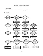
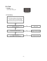
Page 17: ...Doesn t the high tension output come out Doesn t the VSC signal Vs ON come out Yes Yes Does high tension output voltage Drop occur When the Y B D Module input connector is removed does output voltage drop occur When the Y Z B D Module input connector is remove does Power Board hightension output voltage Drop occur Yes No No 9 Check the Power Board Output high tension circuit Yes 10 Check the Z B D...

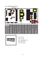
Page 18: ... 18 1 2 42 Power Board Structure T801 Vs Trans T901 Va Trans T112 Low Voltage Trans T501 ST BY Trans T601 PFC Inductor ...

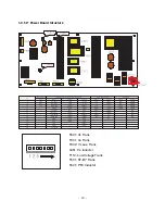
Page 19: ... 19 1 3 50 Power Board Structure T801 Vs Trans T901 Va Trans T902 Vs aux Trans L851 Vs Inductor T112 Low Voltage Trans T501 ST BY Trans T601 PFC Inductor ...

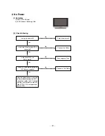
Page 20: ...e Filter Cable to PSU connected Connect the Cable Yes No Is the Fuse F101 on PSU normal Exchange the Fuse Yes No Is the PSU and Main Board with 13P Cable connected Connect a 13p Cable Yes No After the cable connect is remved to Power Board except the EL11 connection cable the AC voltage marking is authorized on manual When ST BY 5V is not operated replace PSU ...

Page 21: ... the power cord and wait until discharge entirely you can watch the LED on a main board through a Back cover If LED is off a discharge is finished Then plug in the power cord again Has it still a problem Is normal the Main board Check voltages of P900 in main board Yes No Is normal the IR board and Local key Exchange the IR and Local key Exchange the Main board Connect cables Yes No No ...

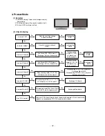
Page 22: ... at Y board are Va Vs normal Are Fuses FS2 FS3 normal Exchange the fuse at abnormal Yes No Yes Yes Exchange Z board Is normal Z board Disconnecting cable P1 P2 P6 at Z board are Va Vs normal Are Fuses FS1 FS2 Normal Exchange the fuse at abnormal Disconnecting cable P1 3 4 105 at X board are Va Vs normal Yes No Yes Is normal X board Disconnecting P1 P3 Va Vs is normal Exchange Right X B D Disconnec...

Page 23: ... normal Exchange the fuse at abnormal Yes No Yes Yes Exchange Z board Is normal Z board Disconnecting cable P1 P2 P6 at Z board are Va Vs normal Are Fuses FS1 FS2 Normal Exchange the fuse at abnormal Disconnecting cable P1 3 4 105 at X board are Va Vs normal Yes No Yes Is normal X board Disconnecting P1 P3 Va Vs is normal Exchange Right X B D Disconnecting P4 P105 Va Vs is normal Exchange Left X B...

Page 24: ... at Scart1 2 or Component2 RGB or Side AV Good Are good some elements C R L or Diode at Sound path Is IC800 good Switching IC Is IC601 good VCT P 1 Speaker part 2 Main board part No No No No Yes Yes Yes Is sound at HDMI Good Is EDID download good Is IC401 good AD9381 No Yes If it dead or short exchange this elements Exchange IC800 No No Exchange IC601 No Is IC801 good Amplifier Exchange IC801 No I...

Page 25: ...e input voltage I2C and CVBS output good Insert the cable exactly Exchange the Tuner Yes No No No Is Gaskets added well Is added the ferrite core at cable Add the ferrite core Add the Gasket Re assemble the SET No No No Yes No Is arranged the cable well Re arrange the cable Don t cross the cable above a X or Z board No 1 Noise appears at RF mode 2 Noise appears at Side AV ...

Page 26: ... display No No Are input voltage I2C and CVBS output good in Tuner Exchange the Tuner No Is VCT P IC good Exchange the VCT P IC No No Is the LVDS cable connected Are good some elements C R L or Diode at path Check the EDID data Yes Yes Insert the LVDS cable exactly If it dead or short exchange this elements Download the EDID data Yes No No Is AD9381 good only _ HDMI Exchange AD9381 IC No Is VCT P ...

Page 27: ... 27 PRINTED CIRCUIT BOARD MAIN TOP CONTROL ...

Page 28: ... 28 MAIN BOTTOM PRE AMP SIDE A V ...

Page 29: ... 29 BLOCK DIAGRAM ...

Page 30: ... 30 EXPLODED VIEW 600 602 601 121 120 570 203 204 206 200 580 205 201 202 400 240 250 430 560 301 304 303 302 501 520 502 300 ...

Page 31: ...R TA 42PC1RV ZJ CIS SET 4980900115B SUPPORTER ASSY AL FILTER RIGHT 42PC1R TA C SKD 304 4980900116A SUPPORTER ASSY AL FILTER LEFT 42PC1 TA 42PC1RV ZJ CIS SET 4980900116B SUPPORTER ASSY AL FILTER LEFT 42PC1 TA C SKD 400 3809900103A BACK COVER ASSEMBLY 42PC1R ANALOG 42PC1RV ZJ CIS SET 3809900103P BACK COVER ASSEMBLY 42PC1 LGEMA ASSY ONLY ANALOG 430 3501900014A BOARD ASSEMBLY D T SPK STAND AP 42DC11 M...

Page 32: ...DD200009AF 0DD200009AF 0DD200009AF 0DZKE00048A 0DR050008AA 0DR050008AA 0DR050008AA 0DR050008AA 0DR050008AA CHIP 2SC3875S ALY BK KEC CHIP 2SC3875S ALY BK KEC CHIP 2SC3875S ALY BK KEC KRA102S KEC REEL TAPING SOT23 50V CHIP 2SA1504S ASY BK KEC CHIP 2SC3875S ALY BK KEC CHIP 2SA1504S ASY BK KEC CHIP 2SC3875S ALY BK KEC CHIP 2SA1504S ASY BK KEC CHIP 2SA1504S ASY BK KEC CHIP 2SA1504S ASY BK KEC CHIP 2SA1...

Page 33: ...1061 C1063 C1064 C1065 C1066 C1068 C1069 C1070 C1071 C1072 C1073 C1074 C111 C112 C113 C114 C115 C116 C117 C118 C119 C120 C124 C125 C126 C128 C131 C134 C135 C137 C138 C141 C142 C159 C162 C163 C164 C172 C173 C174 C175 C309 C310 C311 C312 C313 C316 C317 C332 C333 C334 0CK104CK56A 0CK103CK56A 0CK103CK56A 0CE107WF6DC 0CE107WF6DC 0CE107WF6DC 0CE107WF6DC 0CK104CK56A 0CE476WF6DC 0CE227WF6DC 0CK104CK56A 0C...

Page 34: ...T NO DESCRIPTION C520 C521 C522 C523 C524 C525 C605 C606 C607 C608 C609 C610 C611 C612 C613 C614 C615 C616 C617 C618 C619 C620 C621 C622 C623 C624 C625 C626 C627 C628 C629 C630 C631 C632 C633 C634 C635 C636 C637 C638 C643 C645 C647 C648 C649 C650 C651 C652 C653 C654 C655 C657 0CK104CK56A 0CC271CK41A 0CC271CK41A 0CE476WK6DC 0CK104CK56A 0CE107WF6DC 0CK104CK56A 0CK104CK56A 0CK104CK56A 0CK104CK56A 0CK...

Page 35: ...O DESCRIPTION C766 C800 C801 C802 C803 C804 C806 C807 C816 C820 C821 C822 C823 C824 C825 C827 C828 C829 C830 C831 C832 C833 C834 C835 C836 C838 C839 C840 C842 C845 C848 C849 C850 C851 C853 C854 C855 C856 C857 C858 C859 C860 C861 C862 C863 C864 C865 C866 C867 C868 C869 C906 0CK106EF56A 0CE107WF6DC 0CK103CK56A 0CE226WF6DC 0CK105CF94A 0CK105CF94A 0CK105CF94A 0CK105CF94A 0CK225DK94A 0CK225DK94A 0CK475...

Page 36: ... 1608 50V 10 R TP X7R 0 01UF 1608 50V 10 R TP X7R 0 01UF 1608 50V 10 R TP X7R 0 01UF 1608 50V 10 R TP X7R 0 01UF 1608 50V 10 R TP X7R 0 01UF 1608 50V 10 R TP X7R LOCA NO PART NO DESCRIPTION C974 C975 C976 C978 C979 C980 C981 C982 C983 C984 C985 C986 C988 C989 L1004 L801 L802 L808 L809 L910 C1 C2 C3 C4 C5 C6 C7 C8 C9 C10 JK303 JK304 R525 D1004 D750 LD101 SW101 SW102 SW103 SW104 SW105 SW106 0CK103CK...

Page 37: ...2 MAG LAYERS R TP MLB 321611 0500P N2 MAG LAYERS R TP MLB 321611 0500P N2 MAG LAYERS R TP MLB 321611 0500P N2 MAG LAYERS R TP MLB 321611 0500P N2 MAG LAYERS R TP MLB 321611 0500P N2 MAG LAYERS R TP MLB 321611 0500P N2 MAG LAYERS R TP MLB 321611 0500P N2 MAG LAYERS R TP MLB 321611 0500P N2 MAG LAYERS R TP LOCA NO PART NO DESCRIPTION L920 L921 L924 X600 JK100 JK101 JK102 JK103 JK105 JK106 JK300 JK30...

Page 38: ...MAIN Control Pre AMP ...

Page 39: ......

Page 40: ...Mar 2006 Printed in Korea P NO 38289S0023C ...

Reviews: